Programming Interface
Generally, the Passive model is best for emulating off-the-shelf cables and for eye-diagram validation.
The Redriver model is optimal for general connectiviity or longer connections. It includes a programmable, linear, equalizing redriver which allows USB signal tuning to compensate for insertion and cabling losses.
The USB-C-Switch contains many features. These features are organized into groups called entities. Through these entities we can access the vast features of the USB-C-Switch.
A complete list of all entities and functions can be found in the Module Entities page.
Software Control
Software control of the features of the USB-C-Switch is done with the BrainStem API via a BrainStem link. BrainStem links are done over USB and can be established via the Control Port. After this port is connected to a host machine, a user can connect to it via software API:
stem.link.discoverAndConnect(USB)
When multiple Acroname devices are connected to a host, connecting to a specific hub can be done by providing the hub serial number. Further, all connected devices can be found using
brainstem.discover.findAllModules(USB) (Python)
Acroname::BrainStem::Link::sDiscover() (C++)
Cable Flip
A key feature of the USB-C connector is its symmetric design allowing for insertion in either orientation. This makes the USB-C connector user-friendly yet complicates the development of devices using the USB-C standard. The orientation is defined by the cable or downstream device in the system; more specifically, by components inside of the USB-C male plug of a connection. The USB-C specification makes determining connector orientation a responsibility of the active devices in the system.
With an Acroname UOC cable, the USB-C-Switch enables the unique ability to affect a cable orientation flip. When this orientation flip occurs, it will appear to connected devices that the orientation of their connection has reversed. Most USB-C devices with a female socket will include at least one set of muxes in order to route signal to the correct side of the socket based on the orientation of the cable. When testing such a system it is import to test both orientations to ensure that these internal muxes are functioning. The USB-C-Switch allows flipping of USB-C cable connections to be programmatically automated.
Depicted below are the flip and no-flip setting for full-featured cable and device
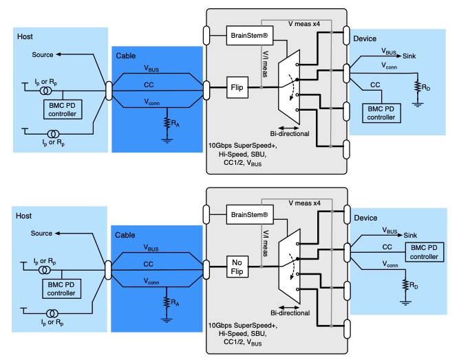
A UOC should be used on either the common port or mux port to enable automated cable flips. The UOC should be connected to the device under test.
When not using the cable flip feature, any standard USB-C cable can be used on both sides of the USB-C-Switch. The orientation of the cables need to be matched in order to facilitate a connection through the switch.
Keep-Alive Charging (KAC)
It is common to use battery powered devices on either side of the USB-C-Switch. When these devices are not in the active path, either on the common or mux side, the device battery may discharge. The USB-C-Switch has the unique feature of Keep-Alive Charging (KAC) for the mux channel connections.
Below is a diagram for the USB-C-Switch KAC capability:
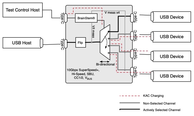
When KAC is enabled, the KAC circuit connects power from the control port VBUS to all non-selected mux channel VBUS lines. KAC power is applied only to inactive mux channels and is not applied to the actively selected mux channel since the actively selected channel has a power path to the common port. KAC is automatically disabled when mux split mode is enabled.
Mux Modes
Default Mode
The default behavior of the USB-C-Switch is to act as a port selector, where all USB-C lines are connected between the common port and one selected mux channel.
Channel Priority Mode
In channel priority mode, the USB-C-Switch automatically selects the lowest-numbered mux port where VBUS is detected, enabling simple automatic host selection. Note that this will only work with USB A-to-C cables, since VBUS is not immediately available on USB-C to USB-C connections.
Split Mode
In some cases, it is desirable to split the connections in a USB-C cable and route them to different mux paths. A common application is to be able connect a USB device to a host machine for USB data while connecting VBUS charging from a device specific charger.
Split mode gives control over individual signal groups, allowing each group to be connect to a mux channel. VBUS can be connected to any combination of mux channels or disabled on the mux channels. Signal groups under Split control assignment are: VBUS, SSA (TX1+/-, RX1+/-), SSB (TX2+/-, RX2+/-), HSA (D+/-, Side A), HSB (D+/-, Side B), CC1, CC2, SBU1, and SBU2.
A basic example of the USB-C-Switch Mux split mode is depicted.
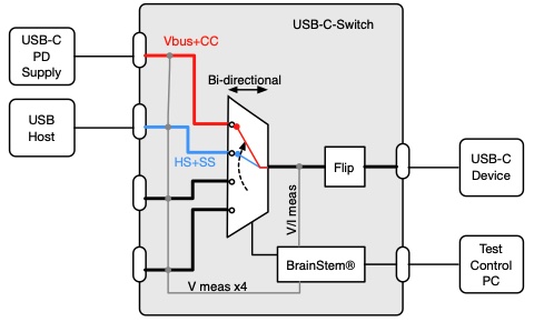
When split mode is enabled, USB-C-Switch will automatically disable the Keep-Alive-Charging (KAC) feature.
Device Drivers
The USB-C-Switch leverages operating system user space interfaces that do not require custom drivers for operation on all modern operating systems including Windows, Linux and MacOS X. With a connection between a host PC and the USB-C control port, the host PC will recognize a USB full-speed device named “USBCSwitch”.
Legacy operating systems like Windows 7 may require the installation of a BrainStem USB driver. Installation details on installing USB drivers can be found within the BrainStem Development Kit under the “drivers” folder.