Appendix III: BrainStem Networking
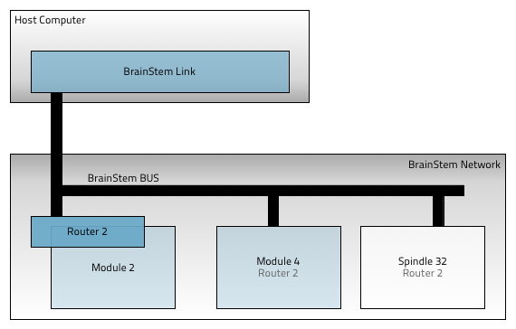
The BrainStem bus is the network backbone of the BrainStem network. Most BrainStem modules, including all MTM modules, use an I2C as the hardware transport. The brainstem network is a multiple master I2C fast mode plus (FM+, 1MHz) network. Traffic on this bus generally follows the specification of the BrainStem protocol. Third party devices can be connected to this network, but it is most common to connect I2C peripherals to a BrainStem module’s peripheral I2C ports.
BrainStem networks closely mirror standard I2C networks, but aren’t necessarily always on an I2C physical network. For example, BrainStem network as described below may use a CAN bus physical network.
Module Addresses
BrainStem devices rely on having a unique module address on the bus that following I2C conventions. The Brainstem module address is a single unsigned-byte, and can take even (non-odd) values from 2 to 254. Each class of BrainStem module has a specific default base address, listed in the table below. A software offset to this address can be set with the BrainStem API, and MTM modules include a set of hardware offset pins which can be used to modify module addresses with external pin connections.
BrainStem Model
Default Base Address
2
4
6
8
10
12
14
16
Hardware Offsets
Hardware offset pins are useful when more than one of the same type of module (i.e. modules with the same base address) are installed on a single BrainStem network. Applying a different hardware offset to each module of the same type the modules to seamlessly and automatically be configured on the network for inter-module communication. Further, modules can be simply swapped in and out of the network without needing to pre-configure a module’s address before being added to a network. Finally, when a system has more than one of the same type of module in a network, the module’s hardware offset can be used to determine the module’s physical location and thus its interconnection and intended function.
Each hardware offset pin can be left floating or pulled to ground with a 1kΩ resistor (or smaller) Pins can also simply be shorted to ground. Pin states are only read when the module boots, either from a power cycle, hardware reset or software reset. The hardware offset pins are treated as an inverted binary number which is multiplied by 2 and added the to the module’s base address. The hardware offset calculation is detailed in the following table.
Pin0 |
Pin1 |
Pin2 |
Pin3 |
Address Offset |
Base Address |
Final Address |
|---|---|---|---|---|---|---|
NC |
NC |
NC |
NC |
0 |
4 |
4 |
0 |
NC |
NC |
NC |
2 |
4 |
6 |
NC |
0 |
NC |
NC |
4 |
4 |
8 |
NC |
NC |
0 |
NC |
8 |
4 |
12 |
NC |
NC |
NC |
0 |
16 |
4 |
20 |
0 |
NC |
NC |
0 |
2+16=18 |
4 |
22 |
Router Addresses
In addition to the module address, each BrainStem device has a network router address. The router address tells the module which BrainStem in the network is connected to the host; i.e. which BrainStem device is acting as the network gateway. If the router address of the module is set to its own module address, then it will send heartbeat traffic and route host-bound traffic from the BrainStem network through its transport link (e.g. USB or Ethernet). If a module’s router address is different from it’s module address, it will route any communication intended for the host computer to its router’s address on the BrainStem network.
By default, each BrainStem’s router address is set to its default base address plus any offset. In this way, each module will communicate over its transport link out of the box. In order to have multiple BrainStem modules communicate across a BrainStem network over one transport link, each module needs have its router address configured. The BrainStem API provides a simple mechanism to quickly configure the router address of all modules on the same BrainStem network: routeToMe.
Setting up a BrainStem Network
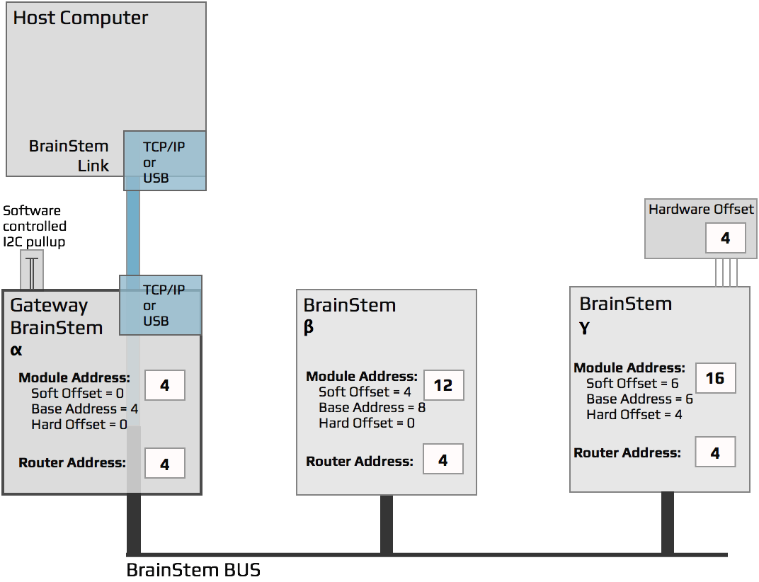
This section of the appendix will walk you through setting up the network shown in the figure below. This is fairly typical network containing three BrainStem devices since it represents a fully populated MTM development board.
Out of the Box
In the example above the Routing or Gateway BrainStem (α) is set to route through itself; i.e. its module and router addresses are equal. This is the setup that comes with the BrainStem out of the box. To complete the example, two more BrainStem devices are needed and they will have their router and address software offsets changed (described below).
I2C Pull-ups
Most BrainStem use an I2C physical network. I2C relies on bus pull-ups resistors. BrainStem modules have built-in 330Ω pull-ups to 3.3V which should allow for communication at 1Mbps. There should be no other pull-ups on the network.
Configuring module routers: the quick way
The system entity contains the entity routeToMe. Calling this from a linked module will temporarily configure all modules on the same BrainStem network to route to the linked module. For example, using the setup from above, we can simply connect to the α module:
>>> import brainstem
>>> alpha = brainstem.stem.MTMUSBStem() # or the appropriate module type
>>> alpha.discoverAndConnect(brainstemlink.Spec.USB)
Then we tell all other modules to route their traffic to the α module:
>>> alpha.system.routeToMe(1)
After this, all modules in the network will start recieving and sending heartbeat traffic, and can be connected from the host:
>>> beta = brainstem.stem.MTMIOSerial()
>>> beta.connectThroughLinkModule(alpha)
Similarly, the γ module can be constructed and connected. All features and abilities of the networked modules are now instantly available to the host software as if they were directly linked the host. This powerful networking allows large networks of modules to be controlled from a single host link.
Setting and saving address offsets and router: the hard(er) way
If it is desirable to configure modules to change their module address or router setting even through power cycles or resets, the BrainStem API provide and interface for directly setting and saving the address offset and the router of each module. This method is more complicated than the routeToMe interface, but is available to provide flexibility for complex network setups. Never worry, if a device’s router address is saved to a non-default value simply creating a link directly to that module (e.g. via USB) will temporarily re-configure its route to itself so the link can be functional.
The system entity contains the options for getting and setting the module offsets and router address of the brainstem module. Module offsets and the router address are applied after a system save and reset. The python interpreter code below sets the module and router addresses for the two modules (β and γ). The same exercise can be done in C++ with almost the same code. For this example, we will assume that both β (beta) and γ (gamma) are new modules and that are directly connected via a USB cable. To simplify this process, the modules can be connected and configured one at a time. Importing a few key modules makes the following commands bit shorter:
>>> import brainstem
>>> from brainstem import link
>>> from brainstem import discover
>>> from brainstem.stem import MTMIOSerial # or other modules needed
Then, connecting to the β module is done with:
>>> beta = MTMIOSerial() # or the appropriate module type
>>> beta.connect(discover.findFirstModule(link.Spec.USB)) # connect to beta.
Then set and save the router and module software offsets with:
>>> beta.system.setModuleSoftwareOffset(4)
>>> beta.system.setRouter(4)
>>> beta.system.save()
>>> beta.system.reset() # beta stops communicating here, and will return a timeout on this call.
>>> beta.disconnect() # good practice to always call disconnect
After calling reset, the module will be trying to connect and communicate via the router address we defined. This router address is the module address of α, the gateway BrainStem. As such, all host-bound communication will the routed to address 4 on the BrainStem network, instead of going through the module’s transport link connector.
The following code sets the module software offset and the router settings on γ to match the diagram. Connecting to γ is done in same way as shown above for β, simply changing the module type to the appropriate module being used.
>>> gamma.system.setModuleSoftwareOffset(6)
>>> gamma.system.setRouter(4)
>>> gamma.system.save()
>>> gamma.system.reset() # similarly gamma stops communicating.
>>> gamma.disconnect() # good practice to always call disconnect
Now the BrainStem network is configured as described in the diagram above. Moving the link cable to be connected to α will allow the entire network to show up via a single link cable. We can continue to use the same objects created earlier in this process by simply setting the module address to what was configured. This tells the host software what address the module can be reached at:
>>> beta.setModuleAddress(12) # Set the Module object's address so that we communicate correctly when we reconnect.
>>> gamma.setModuleAddress(16)
Finally we connect directly to the Gateway Brainstem α, and then connect β and γ through α’s link. We should now be able to successfully send commands and receive responses on all three brainstems through the single link connection to α.
# Connect to the gateway BrainStem. All three stem heartbeats should be active.
>>> alpha.connect(discover.findFirstModule(link.Spec.USB))
>>> beta.connectThroughLinkModule(alpha) # Now reconnect the beta and gamma through the gateway module.
>>> gamma.connectThroughLinkModule(alpha)
In Practice
The above example is intentionally complex in order to show the interaction of hardware offsets and software offsets within a BrainStem network. In most applications and with the MTM development board, usually the user will prefer to make minimal changes in order to form the brainstem network.
In a real life use case of an MTM-USBStem acting as the Gateway, and an MTM-IO-Serial and MTM-PM-1 boards acting as the other two devices, the only changes that need to be made are to set the router address of the MTM-IO-Serial, and the MTM-PM-1 to match the MTM-USBStem base address of 4. Each of the modules have unique base addresses so there are no software or hardware offsets to apply. Also, the default object instantiation can be used without having to set the module address.
>>> beta.setRouter(4)
>>> gamma.setRouter(4)
>>> beta.save()
>>> gamma.save()
>>> beta.reset()
>>> gamma.reset()
>>> beta.disconnect()
>>> gamma.disconnect()
>>> beta.connectThroughLinkModule(alpha)
>>> gamma.connectThroughLinkModule(alpha)