Indicators and Connections
Front Panel
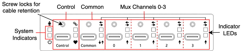
The USB-C-Switch front panel contains all USB ports: Control, Common, and Mux 0-3, along with port and system LED indicators. The control port supports USB Type C power at 5 V, 3 A.
Rear Panel
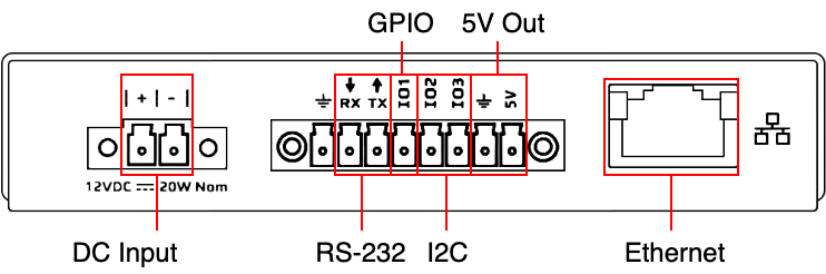
The rear panel contains the Input Power Connector, Ethernet port, and the Expansion Connector.
Input Power Connector
Power for the USB-C-Switch Pro can be provided by the VBUS line on the control port or by external power on the rear panel connection, VINPUT. A Euro-style 2-pin terminal block (“Euroblock”) is used for the external power connection, with pin spacing of 3.81 mm (0.150”).
Expansion Connector
The USB-C-Switch expansion connector is Euro-style 8-pin terminal block (“Euroblock”) with pin spacing of 3.50 mm (0.138”). This interface provides additional mechanisms for expandability and test scenarios. Rail 0 is a software-controlled current-limited fixed 5 V source (disabled by default). IO1 is a general-purpose input and output that can also be configured as a selector to cycle through Mux channels.
Connection Name |
Pin Number |
Description |
|---|---|---|
GND |
1 |
Ground |
RX |
2 |
RS-232 Serial Receive (data to USBCSwitchPro) |
TX |
3 |
RS-232 Serial Transmit (data from USBCSwitchPro) |
IO1 |
4 |
General Purpose Input//Selector |
IO2 |
5 |
I2C SDA |
IO3 |
6 |
I2C SCL |
GND |
7 |
Ground |
5V (Rail 0) |
8 |
Current-limited 5 V source |
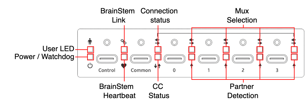
LED Indicators
Type |
Icon |
LED Name |
Color |
Description |
|---|---|---|---|---|
System |
|
User LED |
|
User-controllable LED |
|
Power/Watchdog |
|
Alternating Red and Magenta when powered |
|
Control |
|
BrainStem Link |
|
Link present |
|
BrainStem Heartbeat |
|
Blink when Heartbeat received |
|
Common |
|
Connection Status: Solid = connected |
|
Unflipped |
|
Flipped |
|||
|
Partner detection |
|
VBUS present or PD negotiated |
|
Mux Ports |
|
Mux selection: Solid = enabled Blinking = disabled |
|
Channel selected |
|
Split mode |
|||
|
Partner Detection |
|
VBUS present or PD negotiated |
|
Ethernet |
Left |
Ethernet Activity |
|
Blinks with Ethernet activity |
Right |
BrainStem Link |
|
BrainStem connection established |


Power
The USB-C-Switch Pro can either be bus-powered via the Control Port, or through the 12 V DC input using the included power adapter.
Unit Reset
The USBC-Switch Pro can be reset to factory default settings using the reset button on bottom of the unit. Pressing the reset button once will restart the USBC-Switch Pro as if it had been power cycled. To restore factory default settings, press twice within 5 seconds.