Functionality
Overview
The USB-C-Switch Pro has 6 USB-C ports: 1 Common port, 4 Mux Ports, and a dedicated Control Port. Software control manages signal routing and other port-level features. Each USB-C-Switch Pro is addressable and controllable from a host system via USB (Control Port), net (TCP/IP), I2C, or RS-232. Once connected, a BrainStem® link is established to the onboard controller, enabling software control through the BrainStem API. This API provides full access to all module functionality from a host system.
USB Ports
The Common and Mux ports of the USB-C-Switch Pro implement separate, independently-switched USB HS and SS data, CC, VCONN and current-limited VBUS lines. USB power, HS data and SS data can be independently disconnected for advanced USB testing applications. The USB-C-Switch Pro has a dedicated control channel on the Type C connector labeled “Control”. This is a high-speed USB 2.0 connection for BrainStem interface and power delivery only. No other USB traffic can flow on this connection.
Port-level features are controlled by the USB Entity, while Mux port channel selection, port priority, and split mode are controlled by the Mux Entity.
Port |
Index |
|---|---|
Mux 0-3 |
0-3 |
Common |
4 |
Control |
5 |
Cable Orientation
A key feature of USB-C is its reversible connector, allowing insertion in either orientation. In a standard USB-C cable, only one of the CC lines and one HS pair are wired through. Orientation is defined by the male plug, which connects only one of the receptacle’s two CC (Configuration Channel) pins through the cable. The connected device detects which CC pin is active and routes signals accordingly.
Note
In normal operation, standard USB cables on the Mux and Common sides of the Switch need to be in the same orientation so you may need to flip one of the cables to enable the connection.
Cable Flip
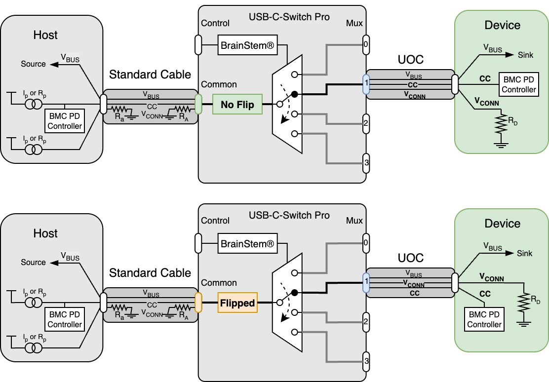
In normal operation, the USB-C-Switch Pro connects signals directly from the Common port to the active Mux port — side A to A and side B to B. The switch can also invert this mapping programmatically, rerouting CC, VCONN, SBU, and USB 2/3 data lines so that side A of the Common port connects to side B of the Mux port (and vice versa). This “cable flip” operation mimics physically reversing the connection between Common and Mux ports.
When used with an Acroname Universal Orientation Cable (UOC), cable flip enables automated testing of both sides of a USB port.
Depicted below are example block diagrams of the flip feature when connecting a host through a standard full-featured, non-marked cable to a direct-connected downstream device. USB SS, HS and SBU lines are also routed, but omitted from the diagram for clarity.
The UOC should be connected to the device under test and either the Common port or Mux port, depending on whether the DUTs or testers are being multiplexed.
UOC Selection
Device USB-C ports either short sides A and B USB 2.0 (HS) data lines or use a mux to keep the two sides electrically independent. Choose the UOC that matches your DUT port.
Two UOC cable types are included:
C70: routes both CC lines and two HS pairs, for devices with muxed USB 2.0 sides
C67: routes both CC lines and one HS pair, for devices with shorted USB 2.0 sides
When using C67, it may be necessary to flip the cable at the Switch end to establish a USB 2 connection.
Alt-Mode Configurations
For Alt-modes, the pin mappings and directions may affect connectivity and functionality. In many cases, the connected devices will simply negotiate through the switch. However, when using DisplayPort Alt Mode, USB4, or ThunderBolt 3, some functional groups need to be assigned a specific direction.
In HubTool:
If device VBUS is not active, toggle cable flip or check cable orientations
Under Alt Mode, select the corresponding configuration depending on whether the host is on the Common or Mux port and the protocol used. For 2-lane DP and USB4 / TB, it may be necessary to try the inverted and non-inverted option.

Alt-mode configuration menu in HubTool
Keep-Alive Charging (KAC)
It is common to use battery powered devices on either side of the USB-C-Switch Pro. When these devices are not in the active path, the device may go into low-power or sleep mode, or its battery may discharge. The USB-C-Switch Pro has the unique feature of Keep-Alive Charging (KAC) for the Mux channel connections. KAC is only active when USB-C-Switch Pro is connected to its external DC power supply.
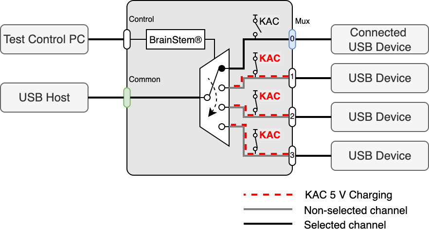
When KAC is enabled on an inactive Mux port, the port’s VBUS connects to the KAC circuit to provide 5 V 500 mA. The KAC circuit does not provide USB power-delivery (USB-PD), USB battery charge specification (BC1.2) or QuickCharge® to the selected ports. The KAC circuit has thermal and overcurrent protection and will stop providing power if limits are exceeded. KAC must be disabled and re-enabled to restore charging. KAC is automatically disabled when mux split mode is enabled.
Mux Split Mode
The default behavior of the USB-C-Switch Pro is to act as a port selector, where all USB-C lines are connected between the common port and one selected mux channel. In some cases, it is desirable to split the connections in a USB-C cable and route them to different mux paths.
Split mode gives control over individual signal groups, allowing each group to be connect to a mux channel. VBUS can be connected to any combination of mux channels or disabled on the mux channels.
Common application include:
Providing a data connection between a USB device the host machine while connecting VBUS charging from a device-specific charger on a different port.
Splitting USB HS and SS lines to provide two independent device connections to a single host port.
Signal groups under Split control assignment are:
VBUS
SS(TX 1/2 +/-, RX 1/2 +/-)
HS (D+/-),
CC1, CC2, SBU1, and SBU2
When split mode is enabled, VBUS can be assigned to multiple Mux ports simultaneously, which is useful for powering multiple devices. However, Acroname recommends that VBUS be assigned to only one mux channel. Caution should be used with multi-point VBUS assignments as it is possible to apply a VBUS voltage to a device that has not negotiated for high VBUS voltages which could damage connected devices.
When split mode is enabled, USB-C-Switch Pro will automatically disable the Keep-Alive-Charging (KAC) feature.
Warning
Split mode can create connections and configurations not possible or compliant with standard USB equipment. Using this feature could cause unexpected voltages to be applied to devices which may damage connected equipment
Ethernet Control
The USB-C-Switch Pro can be managed over Ethernet using the HubTool application, BrainStem API, REST interface, or built-in web interface. Connections are made through the Ethernet jack using TCP/IP sockets and are supported on the local link segment only.
By default, the USB-C-Switch Pro acts as a DHCP client and will receive an IP address from a DHCP server. If no server is detected, the USB-C-Switch Pro falls back to a static IP address of 192.168.44.42. In static mode, the host computer interface IP must be set to an address in the 192.168.44.x range. The DHCP client is limited to hosts on the local link and does not operate across network bridges or gateways.
The USB-C-Switch Pro responds to ICMP “ping” requests including broadcast pings. The BrainStem API interface performs a discovery process prior to establishing communication by sending a UDP multicast request on port 9888. The USB-C-Switch Pro responds with a message to UDP port 9889. The USB-C-Switch Pro listens for socket connections on TCP port 8000. The Rest interface uses TCP on ports 9005 and 9006
Host firewall rules must allow:
Outgoing UDP multicast on port 9888
Incoming UDP responses on port 9889
Outgoing TCP connections to port 8000
Incoming / Outgoing TCP connections on ports 9005 and 9006