OVERVIEW
Buttons are an ideal basic example because they are easy to implement and are used in many applications that the user needs to interact with the system. This example demonstrates how easy it is to configure the BrainStem to read digital pin data and use that data to execute another function. The button will be used to toggle the User LED for this example.
BrainStem application examples require the BrainStem Support package.
THE SETUP
There are several hardware components needed for this example:
- 40-Pin EtherStem 1.0 Module
- 40-Pin Breakout Board
- Ethernet Cable
- Button
- Resistor
BUTTONS AND RESISTORS
A button has an open state and closed state. Since a microcontroller needs to see a definite high or low voltage level at the digital input, a button requires a pull-up or pull-down resistor.
A resistor placed between a digital input and the supply voltage is called a "pull-up" resistor because it normally pulls the pin's voltage up to the supply. A button placed between the digital input and ground will short the digital input to ground when it is pressed, meaning the voltage seen at the input will be high when the button is open and low when the button is closed.
A resistor placed between a digital input and ground is called a "pull-down" resistor because it normally pulls the pin's voltage down to ground. A button placed between the digital input and the voltage supply will short the digital input to the voltage supply when it is pressed, meaning the voltage seen at the input will be low when the button is open and high when the button is closed.
A pull-up or pull-down resistor can be quite large and still work properly. Values from 1K to 10K are typical.
CONFIGURATION
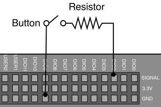
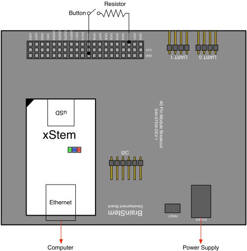
Connect the BrainStem to the development board with a power supply attached and an Ethernet cable connecting the BrainStem to the host computer. Connect a resistor between the signal pin of a DIO [DIO2 for this example] and a button that is grounded.

Detailed View

Wiring Diagram
READING A DIGITAL PIN WITH REFLEX
The Digital class is used to read and set values of the digital pins. The Configuration entity of the Digital class is used to configure the digital pin for input. The State entity is then used to store the current value of the digital pin in a variable. The System class is then implements the LED entity to change the state of the User LED based on the value of the digital pin.
READ A BUTTON STATE USING REFLEX
#include <a40PinModule.reflex>

a40PinModule stem(a40PINSTEM_MODULE);

reflex mapEnable()
{
  char bButtonState = 0;
  stem.digital[2].setConfiguration(0);

  while (bButtonState < 2) {
    stem.digital[2].getState(bButtonState);
    if (bButtonState == 1) {
      stem.system.setLED(true);
    } else {
      stem.system.setLED(false);
    }
  } // end of while loop
} // end of mapEnable
Line 8 - Configures digital pin 2 for input.
Line 11 - Reads the button state and assigns the state to the "bButtonState" variable.
Line 13 - If statement that turns the User LED on if the button is toggles.
Line 15 - Turns the User LED off if the button is not toggled.


