 OVERVIEW
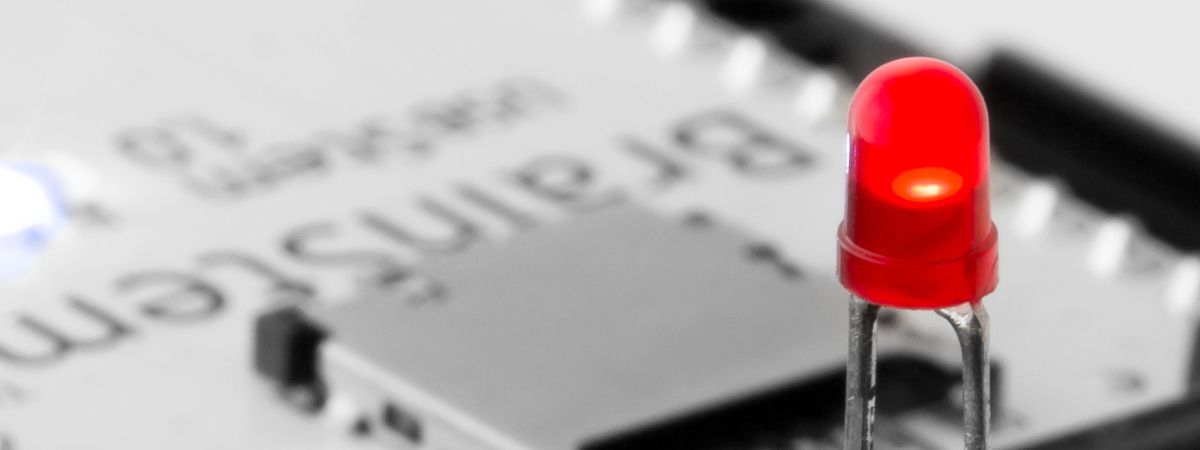
LED's serve many purposes and can range in color from ultraviolet to infrared. They can be used to detect light similar to the light they emit, serve as voltage references, and as a visual reference for active channels. Since LED's have a large range of uses and are conceptually simple to use, popular introductory examples demonstrate the use of digital pins to flash external LED's. The 40-Pin EtherStem 1.0 Module has 12 different digital pins that can be used in this example. Digital pin 2 will be used for this example.
BrainStem application examples require the BrainStem Support package.
THE SETUP
There are several hardware components needed for this example:
- 40-Pin EtherStem 1.0 Module
- 40-Pin Breakout Board
- Ethernet Cable
- Through Hole Standard LED
- 1k-2k Ohm Through Hole Resistor
LIGHT-EMITTING DIODES AND RESISTORS
An LED, or light-emitting diode, requires a supply voltage and current-limiting resistor to work properly. Typical LEDs have an anode (+) side and a cathode (-) side. The LED must be connected with the proper polarity. Sometimes the cathode is indicated by a flat spot on the rim of the base of the LED.
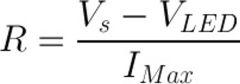
To determine the resistance R necessary to get the desired current through an LED use Ohm's Law:
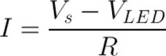
The current, I, that will flow through the LED for a given resistor can be determined using an alternate form of Ohm's Law.
These equations demonstrate why a resistor is needed for LED applications. Without one, the only resistance is the wiring between the supply and the LED, which normally has a very low resistance. By Ohm's Law, a very large current will flow and possibly destroy the LED. As a rule of thumb, a 1K resistor is a good starting value when connecting an LED. If the LED is not bright enough, or too bright, a different resistor can be used. The lower the resistance, the brighter the LED will be.
CONFIGURATION
Connect the BrainStem to the Development Board. Connect the Development board to a power supply and the BrainStem to the host computer. Connect the resistor to the output pin of a DIO [DIO2 will be used for this example]. Connect the resistor to the + side of an LED, and connect the - side to ground.
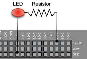
Detailed View
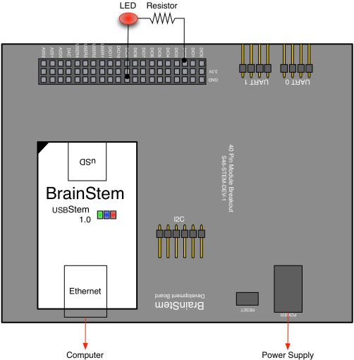
Wiring Diagram
DIGITAL PIN MANIPULATION USING REFLEX
The Digital class allows easy control of digital pin settings through Reflex. For this example, the set option of the State entity is used to toggle an external LED. The System class entity, Sleep, is used to control the length of time between LED toggles.
FLASH AN EXTERNAL LED USING REFLEX
#include <a40PinModule.reflex>
#define DELAY 1000000

a40PinModule stem(a40PINSTEM_MODULE);
reflex mapEnable()
{
  char i = 0;
  for (i = 0; i < 10; i++) {

    stem.digital[2].setState(true);
    stem.system.sleep(DELAY);

    stem.digital[2].setState(false);
    stem.system.sleep(DELAY);

  } // end of for loop
} // end of mapEnable
Line 14 - Sets the state of digital pin 2 to true.
Line 17 - Sets the state of digital pin 2 to false.