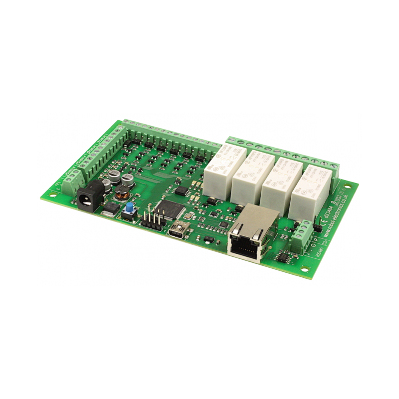
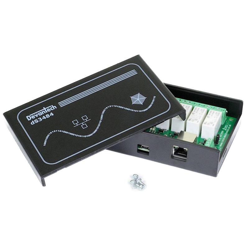
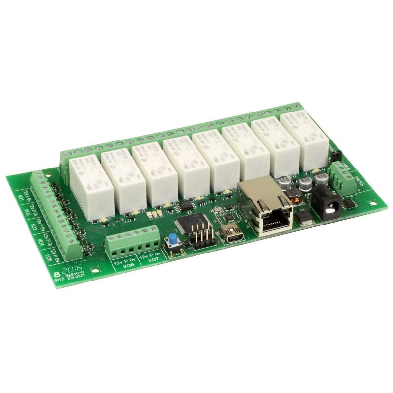
The dS3484 Ethernet controlled relay board provides 8 digital switching I/O channels and 4 voltage-free contact relay outputs with a current rating of up to 16A each. Controlled over TCP/IP via Ethernet or USB for development.
The dS3484 is an Ethernet connected relay module featuring 4 channels of 16Amp 250Vac relays. Each relay has both normally open (NO) and normally closed (NC) as well as the common available on three terminals.
The dS3484 has four built in control methods.
- Primary control method is graphically by using its built in secure website.
- Secondary control may be one of: ASCII - type in commands via a program such as PuTTY.
- Binary - Command set using binary codes
- Modbus – Functions 1, 4, 5 and 15 supported
And if you should wish to modify the supplied firmware – you can. Behind the scenes there is dScript, a powerful multi-threaded operating system and programming language. The supplied firmware is written in dScript as well as HTML, CSS and Javascript on the webpages and the full source is in the separately downloadable dScript support package.
This module can be customized using Devantech’s dScript language, an editor that lets you add your own features and controls. That includes the ability to create a custom webpage with your logo, buttons, and functionality; add a TCP server and respond to incoming TCP requests with custom functions; and include a TCP client to send packets of TCP data to other devices.
LED indication
The dS3484 provides a red LED mounted immediately next to each relay to indicate whether it is in a powered state (LED on), there are also two LED's mounted in the Ethernet connector which will flash with Ethernet traffic. A row of three LEDs, Blue, Green and Red, are available to the user for status indication. There are also 2 LED's for module status, the Red LED lights when the module is in bootloader mode – this is when the IDE is uploading system firmware to the module. The Green LED lights the board begins running user programs. The three user LEDs are available and can be controlled as digitalports 33-35.
- digitalport LedBlue 33
- digitalport LedGreen 34
- digitalport LedRed 35
The “FlashingLeds” example provides a colourful display showing how to use them.
Power supply
The dS3484 requires a 12v DC supply capable of supplying a minimum of 1A. This is most easily provided by a low cost mains adapter. A suitable universal adapter is available on our website and may be ordered along with the modules. Connection is via the 2.1mm DC jack socket. Positive on the center pin.
Operating temperature
-40C to +70C
Hardware
- Serial ports - 2 x TTL level serial ports, 1 x RS485 port..
- Relays - 4 with up to 16Amp @24vdc or 250vac, screw Terminals for N/O N/C and Common contacts
- I/O - 8 channels, your choice of VFC input or NPN output.
- Analogue Inputs - 4 channels of 10-bit A/D.
- Communication - USB for development, RJ45 Ethernet for normal access
- Power - 12V DC jack 2.1mm (adaptor sold separately)
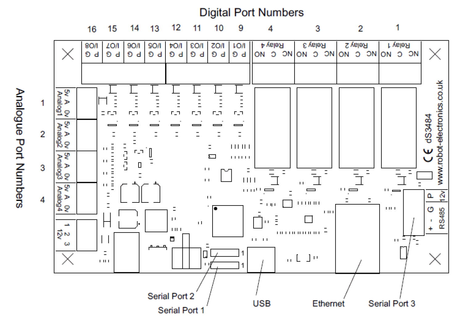
- Ethernet connected module, 10/100Mb auto negotiated.
- 4 x 16Amp 250Vac C/O.
- 12VDC 1Amp supply required. 2.1mm center positive.
- Screw Terminals for N/O N/C and Common contacts
- Controlled graphically by secure webpage or optionally one of ASCII, Binary or Modbus command sets over TCP/IP.
- 8 selectable notifications, up to 100 emails/hour max.
- Control relays on other modules.
- Able to schedule events based on time of day/week
- Count or time events. 20 counts/second Max.
- PCB size – 156mm x 84mm
Power relays
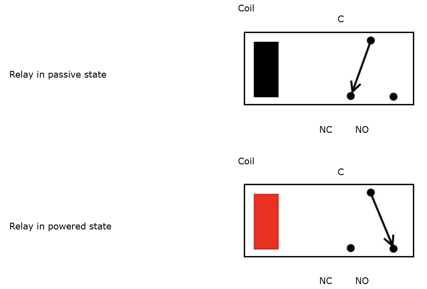
Four 16A volt free contact relays are provided for switching a common input between a normally closed output and a normally open output. The relay coil is powered by the 12vdc incoming supply on user command.
Digital IO
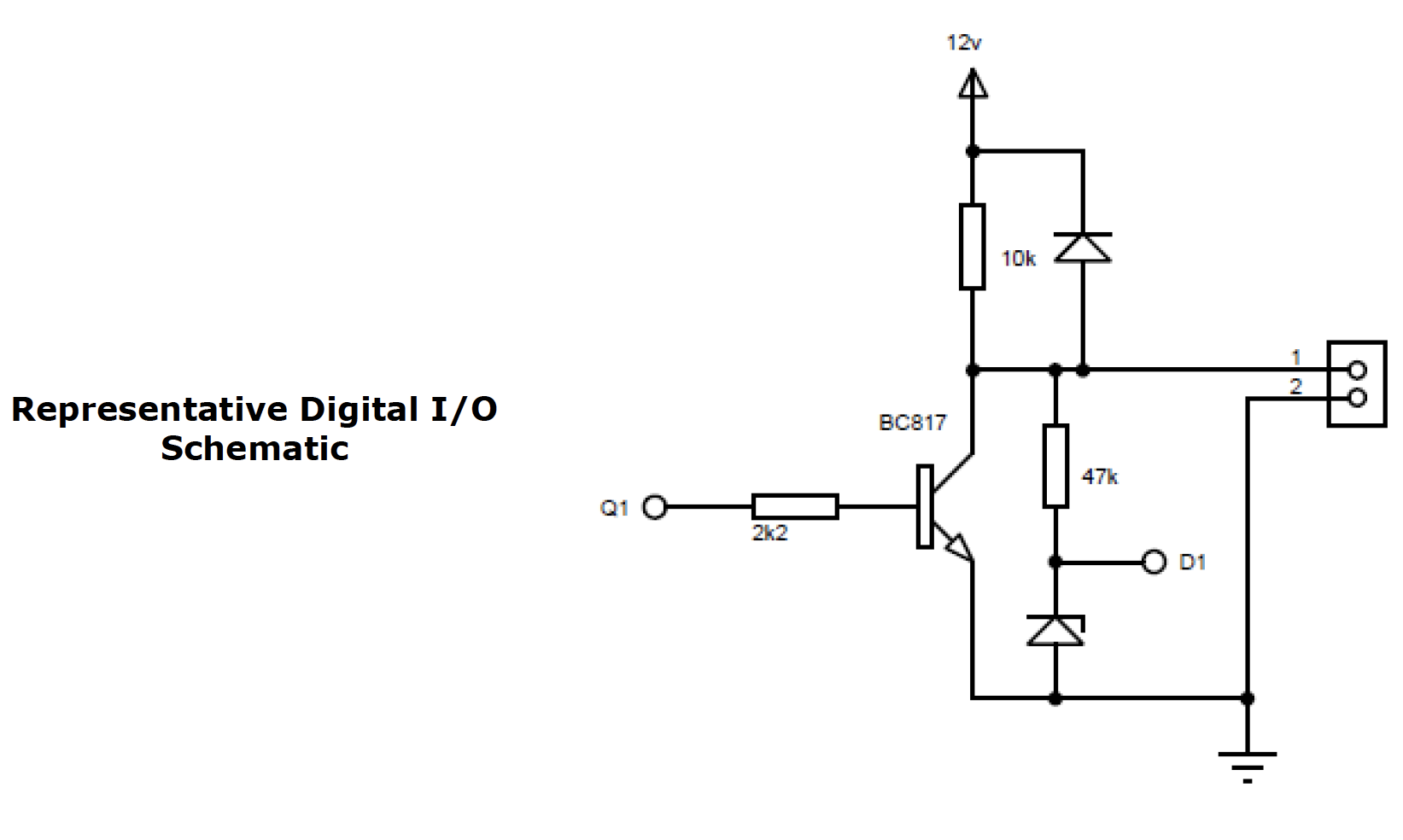
Our Ethernet modules could potentially have many types of outputs. For example the ETH008 only has one type - Relays. The dS3484 has both Relay outputs and NPN Open Collector Transistor outputs. Activating a relay means turning the relay on. Likewise activating an output means turning the transistor on. This will cause it to sink current to 0v ground. If you had an LED connected from the output to 12v (via a resistor of course) it would light up. Other modules (not this one) could have PNP Open Collector Transistor outputs. These types will source current from the supply when active.
So here's the point: Active does not mean a high voltage comes out. It means that the output has been activated. That could result in the output sinking or sourcing current, depending on its type. The outputs will sink current (up to 100mA max.) when active.
The same principle applies to the inputs, these are designed to allow you to directly connect a VFC (Volt Free Contact). This could be from other relay contacts, thermostat contacts, alarm contacts etc. When the contacts are closed the input will read as active. In fact anything that pulls the input pin down to 0v will read as active. Do not think of the I/O in terms of a high or low voltage output. Think of it in terms of Active (or on, something is actively driving the I/O), or inactive (or off, nothing is driving the I/O). It's a subtle point but one you need to be clear on.
If you write inactive or off, the I/O can be used as an input. When you write active or on the transistor turns on and you cannot use it as an input in that state. On power-up, the I/O’s will be off and can be used as inputs.
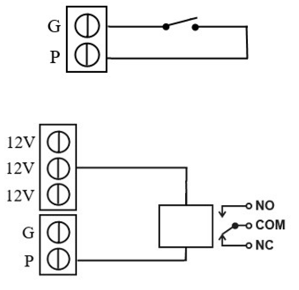
Connection Examples
Example input - connecting a switch
Connecting a simple switch could not be easier, just wire the switch between a pin (P) and ground (G). When the switch closes the input will become active.
Example output - connect a relay
You can connect your own 12V relays, the first coil pin of the relay is wired to the 12V supply terminals on the board, the other is wired to the output pin (P). When the output pin becomes active it is driven down to 0V ground, the relay will have 12V across the terminals and switch so COM is connected to NO.
| Characteristics | ||
| Serial Ports | 3 | |
| Relays | 4 - with up to 16A @ 24VDC or 250VAC, screw terminals for N/O N/C and common contacts | |
| Digital Switching I/O Channels | 8 | |
| Analog Inputs | 4 | |
| Communication | USB for development, RJ45 ethernet for normal access | |
| Power | 12VDC jack, 2.1mm (adapter sold separately) | |
| dScript editor requirements | Windows 7 or later |
|
Add New Review