MTM: Hardware Setup Guide
Thank you for choosing MTM from Acroname! In this blog, we will walk through the hardware and initial setup to get started with a basic evaluation of the BrainStem/MTM platform.
As a start, you will need an MTM Development Board and then relevant MTM modules to use with the Development Board for your project.
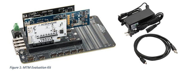
You can purchase boards separately or in a kit. We will start with the MTM Evaluation Kit, which includes:
- (1) MTM Development Board
- (1) MTM USBStem Module
- (1) MTM PM-1 Single-Channel Programmable Power Module
- (1) MTM IO-Serial Module
- (1) 12V/5A power supply
- (1) USB Type A to mini-USB cable

Parts Description
A description of the boards in your system:
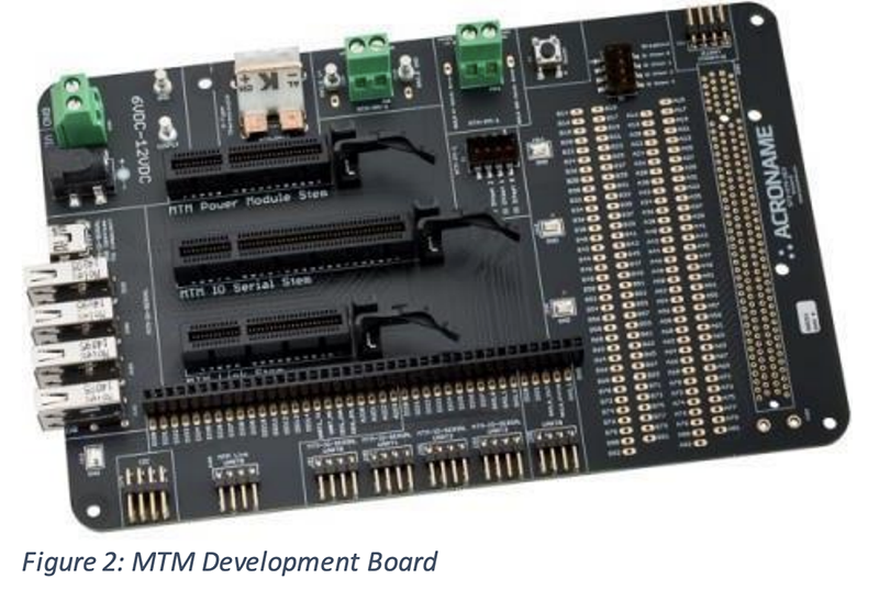
MTM Development Board:
https://acroname.com/products/MTM-DEVELOPMENT-BOARD?sku=S73-MTM-DEV
A breakout board that will allow you to add/remove MTM cards and give you access to relevant signals.
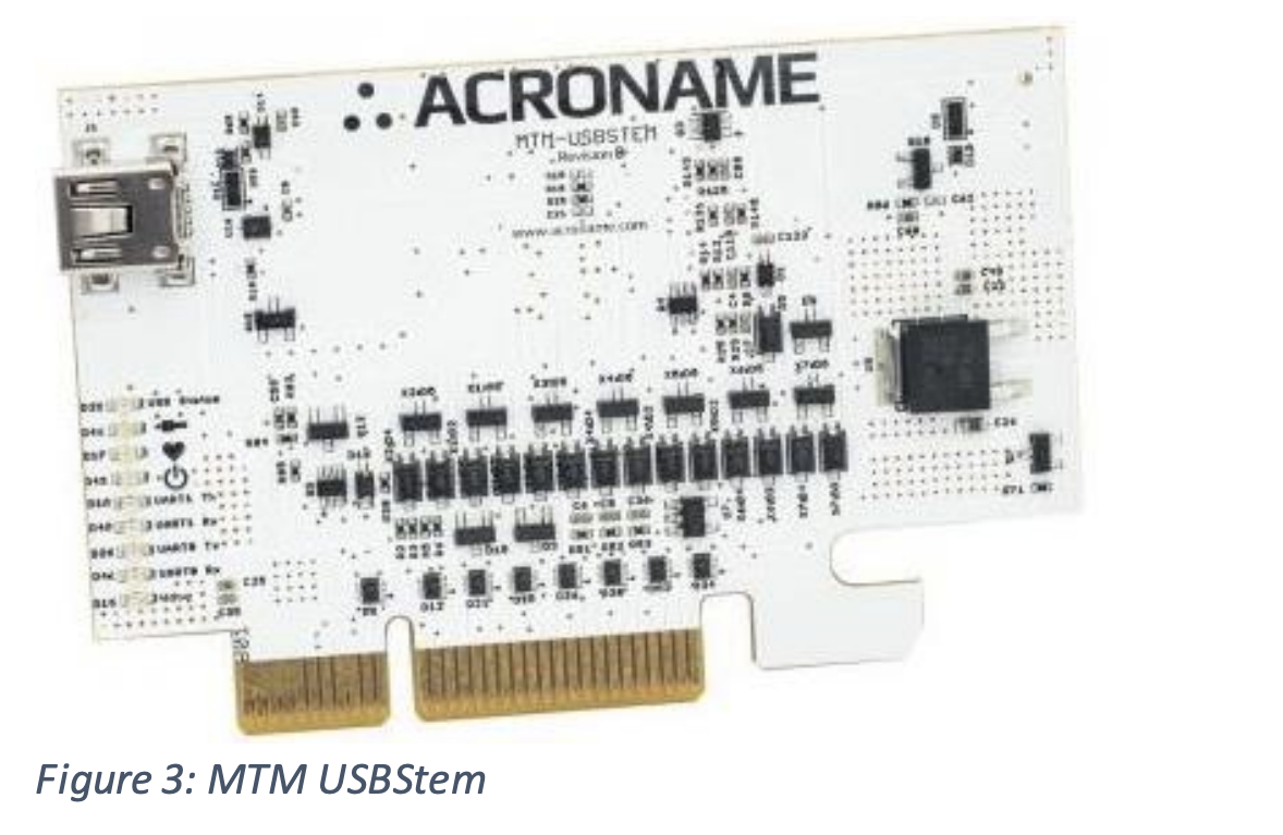
MTM-USBStem:
https://acroname.com/products/MTM-USBSTEM-USB-MICROCONTROLLER-MODULE?sku=S69- MTM-USBSTEM
A general purpose card with 15 digital IOs, 3 analog inputs and 1 analog output, 2 ports of I2C, 2 UARTs and a microSD card slot for user memory/data.
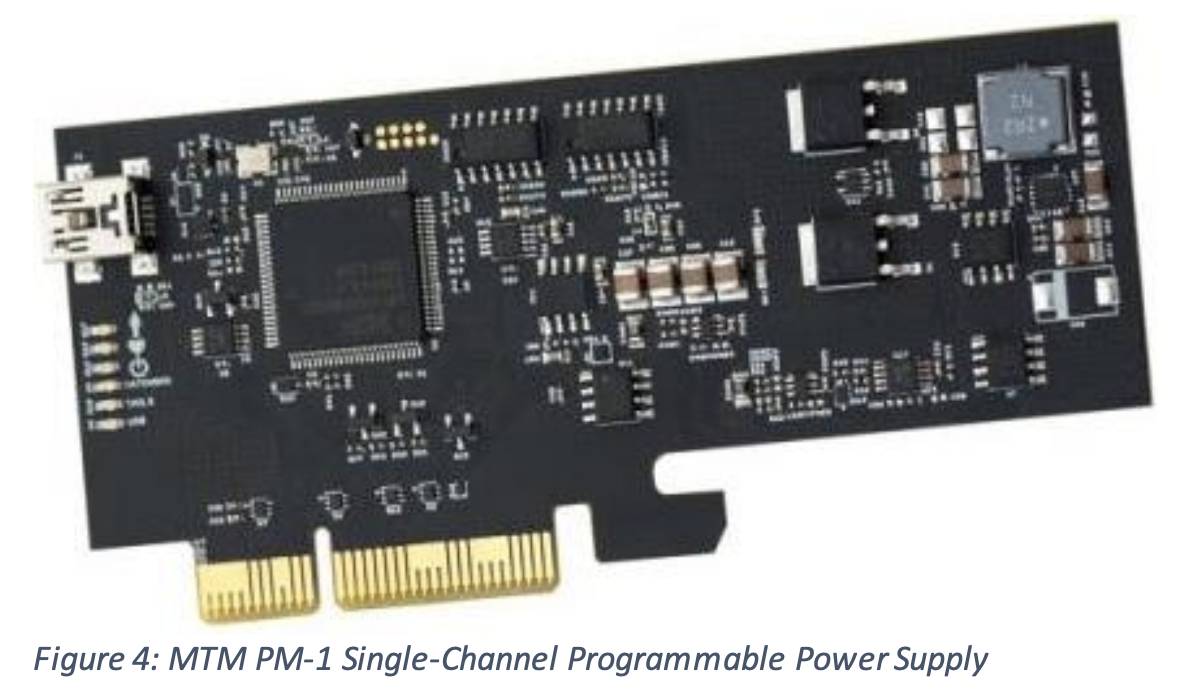
MTM-PM-1:
https://acroname.com/products/ACRONAME-MTM-1-CHANNEL-POWER-MODULE?sku=S65- MTM-PM-1
A single-channel programmable power supply with one regulated (switched or linear) output and one switched output. The MTM-PM1 also has 2 available DIOs, an I2C port, a current mirror output and an optional K-Type thermocouple input (thermocouple capability must be ordered as an option using part number MTM-PM1-TH).
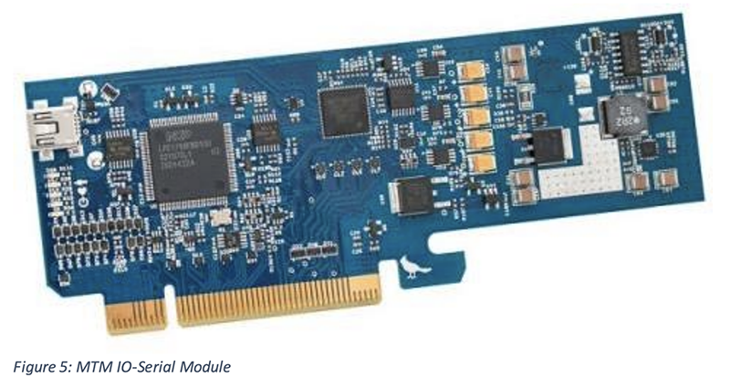
MTM IO-Serial:
Features 2 adjustable IO rails which are split in to two banks. Each of the two adjustable rail banks has 2 UARTs, 1 I2C port and 4 GPIOs – for a total of 4 UARTS, 2 I2C ports and 8 GPIOs. A 4-port software-controlled USB Hub is also built in.
CAUTION: Although these MTM boards use PCIe type connectors, they are NOT PCIe cards and should NEVER be inserted into PCIe slots in a PC or host computer.
MTM Development Board
Slots and Access Points Labeled slots on the MTM Devevelopment Board indicate where the MTM modules should be inserted:
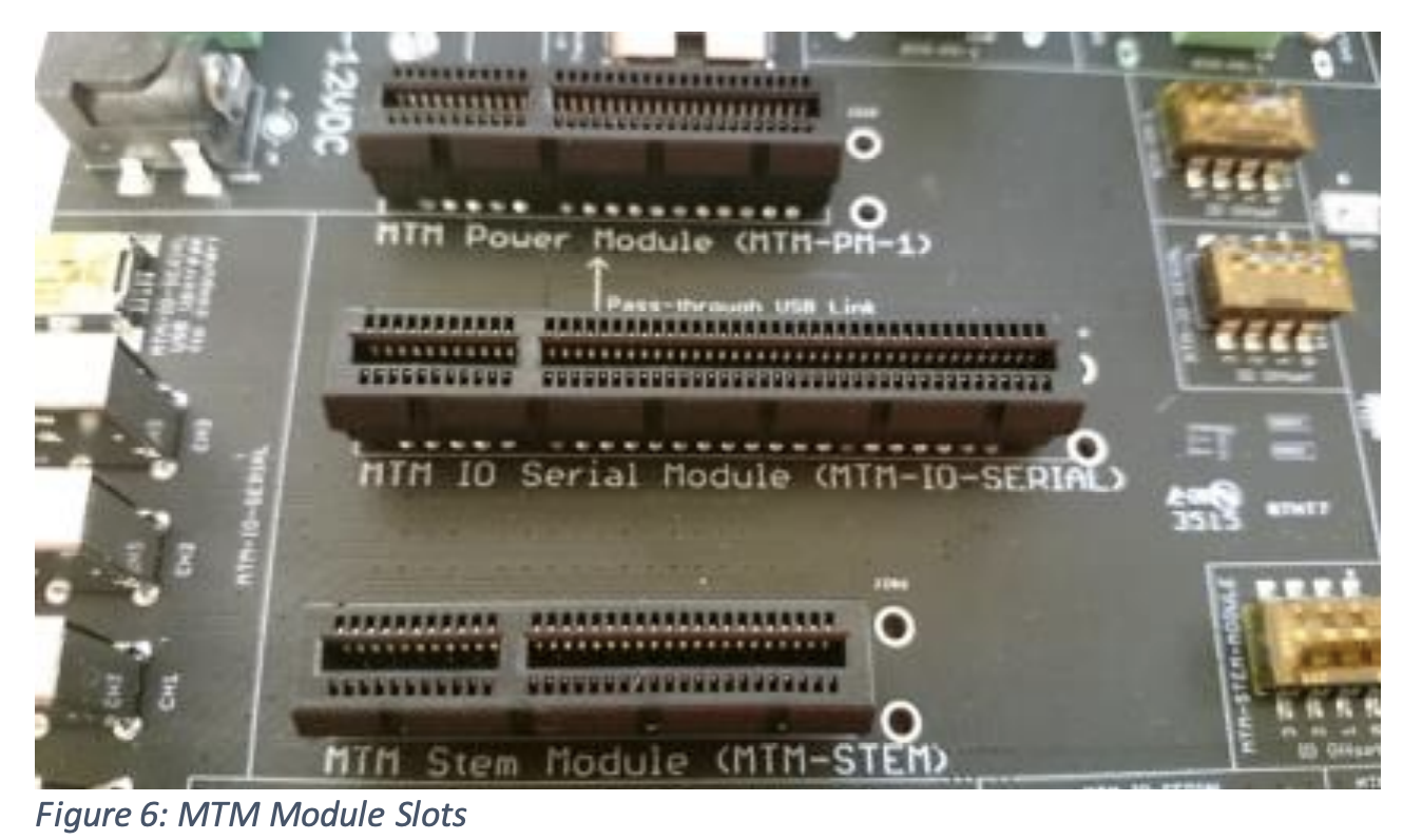
Placing the MTM modules in different slots will not damage the modules, and they will still communicate over the BrainStem network, but the MTM Development Board headers and external connections will no longer carry the signals indicated by the silkscreen labels.
NOTE: The MTM-STEM slot can host either the MTM USBStem Module –or– an MTM EtherStem Module.
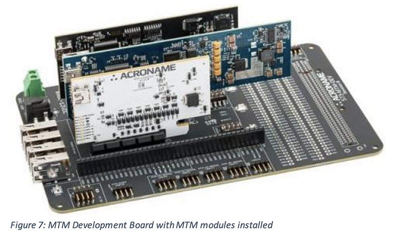
With slots populated, your MTM Development Board should now look like this:
Access Points for MTM Modules
The pertinent connections are available when the MTM modules are placed in the correct slots. We have removed modules from our board to better illustrate the access pins:
MTM Stem GPIOs, Analog IOs, UARTs and I2Cs (applies to the USBStem or EtherStem):
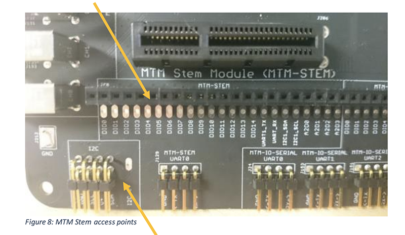
This I2C section (above) provides access to the BrainStem I2C bus. Use this to bridge BrainStem I2C to your system or to another MTM Development Board.
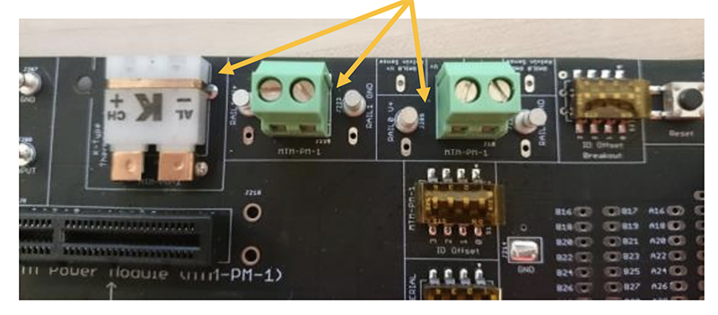
MTM PM-1 Power Rail Outputs and Thermocouple outputs:
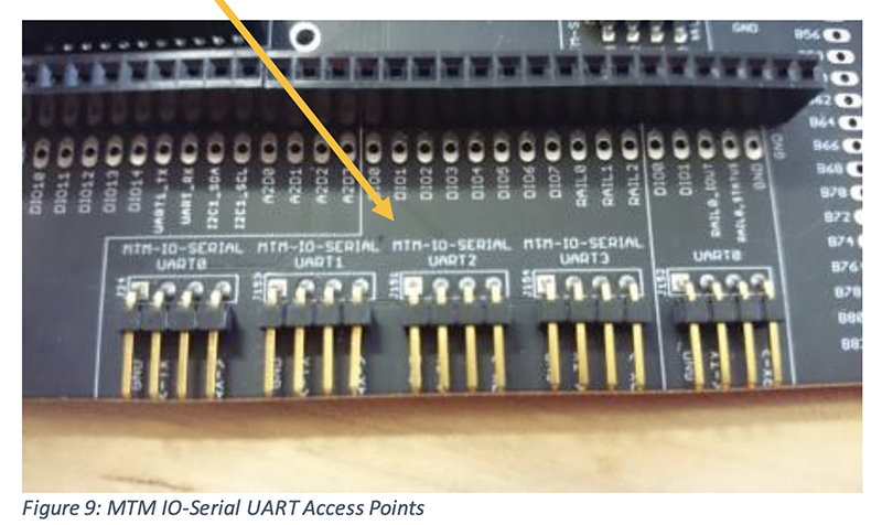
MTM IO-Serial Module IO Rails, GPIOs and UARTs:
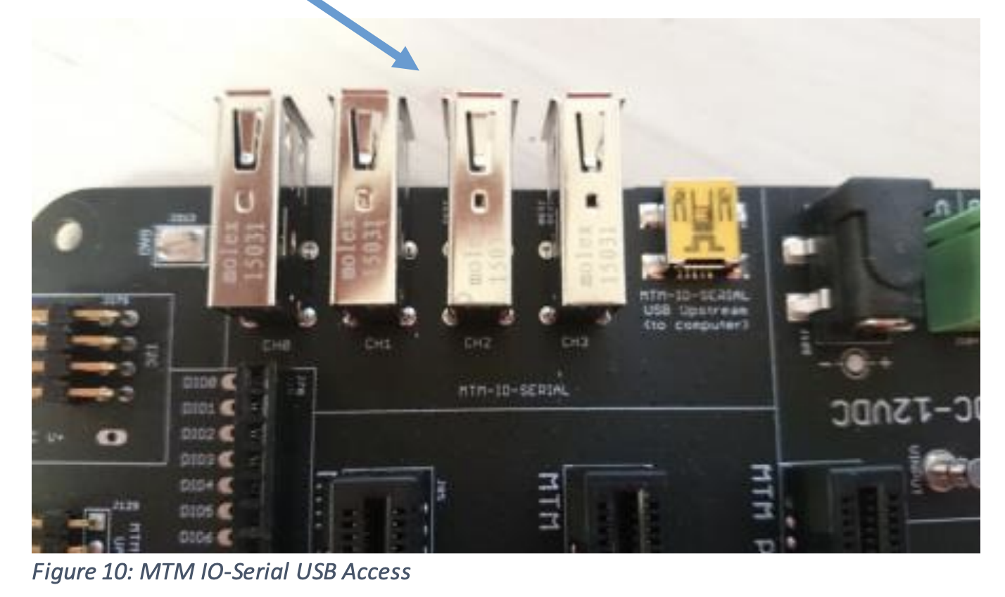
MTM IO-Serial Module USB ports:
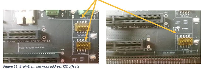
BrainStem Offset DIP Switches:
Make sure that all of the DIP switches on the MTM Development Board are set to 0000. These switches set the I2C address offset for each MTM module slot. If you plan to change the I2C offsets for your MTM modules in your application – or if connecting multiple MTM Development Boards, you can assign different offsets for each module slot here:
Powering On:
Plug in the 12V/5A power supply and then plug the barrel output in to the MTM Development Board here (again, MTM modules were removed for the photo):
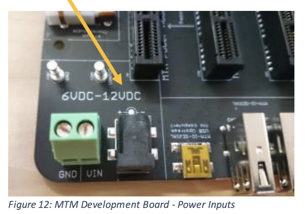
Additional connectors are also provided for alternate external power sources. These should be 6V to 12V in range as shown in the silkscreen.
After powering on, each MTM module should have a both red power LED illuminated and a blue Wdog (watchdog) LED flashing as seen below:
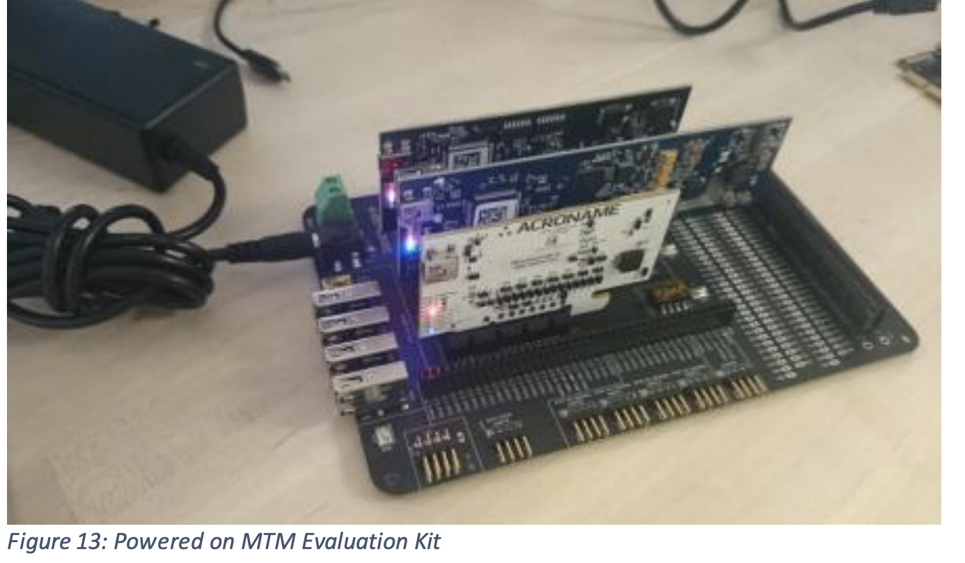
Each MTM module has it’s own built-in RTOS and also supports a USB connection to the host. In your application, you will be able to connect the host to any of the MTM modules available.
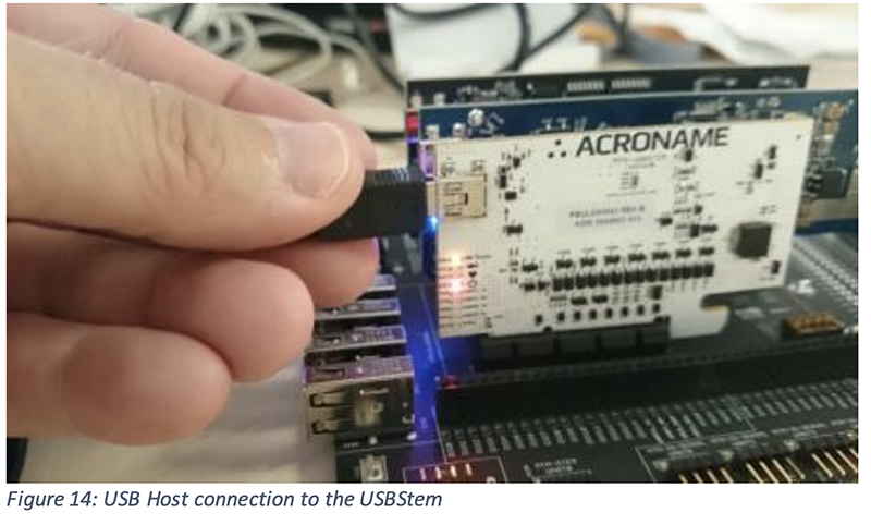
For this exercise, we will be connecting our host to the MTM USBStem.
Please use the USB Type A-to-Mini USB cable to connect your host computer to the USB connection on the MTM USBStem as shown below. The yellow “USB Status” LED should be lit to indicate the MTM module is connected to a host:

Congratulations!
You now have your BrainStem MTM platform up and running. We are now ready to set up software and communicate with the platform.