MTM: Software Setup Guide
Thank you for choosing MTM from Acroname! In this guide, we will walk an initial bring-up and basic evaluation of the BrainStem/MTM platform. By the end of this guide, you will be able to:
- Use USB to access MTM modules over the BrainStem network
- Use the Updater tool to update your MTM modules to the latest firmware and
- Use StemTool to exercise simple functions using resources of the MTM modules:
a. Configuring, setting and reading digital signals
b. Analog measurement of a digital signal
c. Analog measurement of an analog signal
d. Enable BrainStem network routing to access multiple MTM modules
e. Using multiple MTM modules - analog measurement of a power rail
Before you start, you will need an MTM Development Board and the relevant MTM modules that you will be exercising in your project.
See the “Getting Started with BrainStem/MTM: Hardware Setup Guide” document.

Setup MTM Hardware
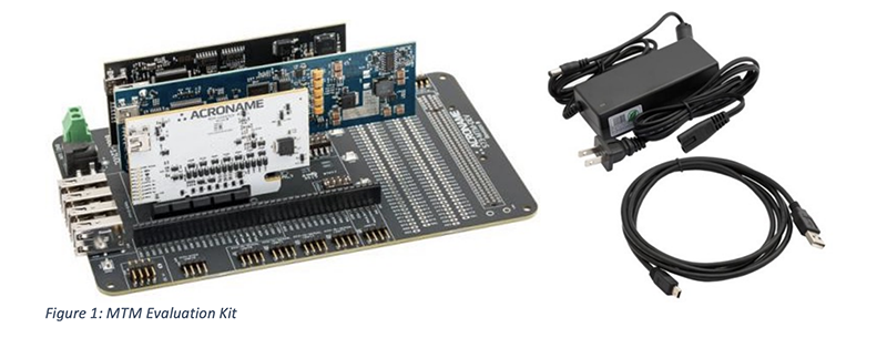
You will need an internet-connected host computer with at least one USB port and running either Windows (7 or higher), Linux or Mac OS X. In this example, we will be running Windows 10. From the Hardware Setup Guide, we assume that MTM Evaluation Kit hardware is available and running:
(1) MTM Development Board
(1) MTM USBStem Module
(1) MTM PM-1 Single-Channel Programmable Power Module
(1) MTM IO-Serial Module
(1) 12V/5A power supply
(1) USB Type A to mini-USB cable
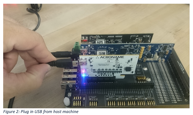
Once your MTM hardware is set up and powered on, you will need to connect one module to your host machine. The connection can be to any of the modules in the MTM Evaluation Kit, but for the first example, we will connect our host to the MTM-USBStem module using mini-B USB edge connector:
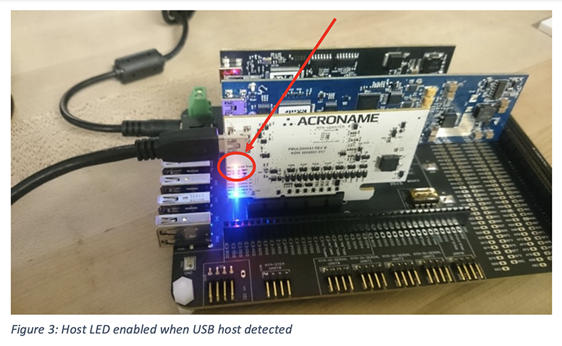
With the host plugged in to the MTM module edge connector, you should now see the yellow “USB Status” LED lit to indicate an active host connection:
Download BrainStem Developer’s Kit
In order to communicate with any of the MTM modules, the BrainStem libraries will need to be installed on the host machine.
Download the latest BDK (BrainStem Developer’s Kit) package from Acroname (www.acroname.com/software)
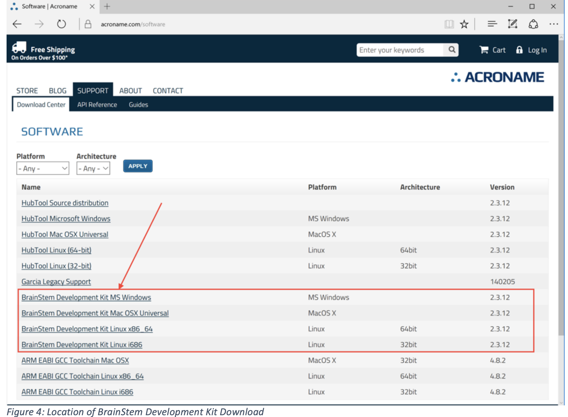
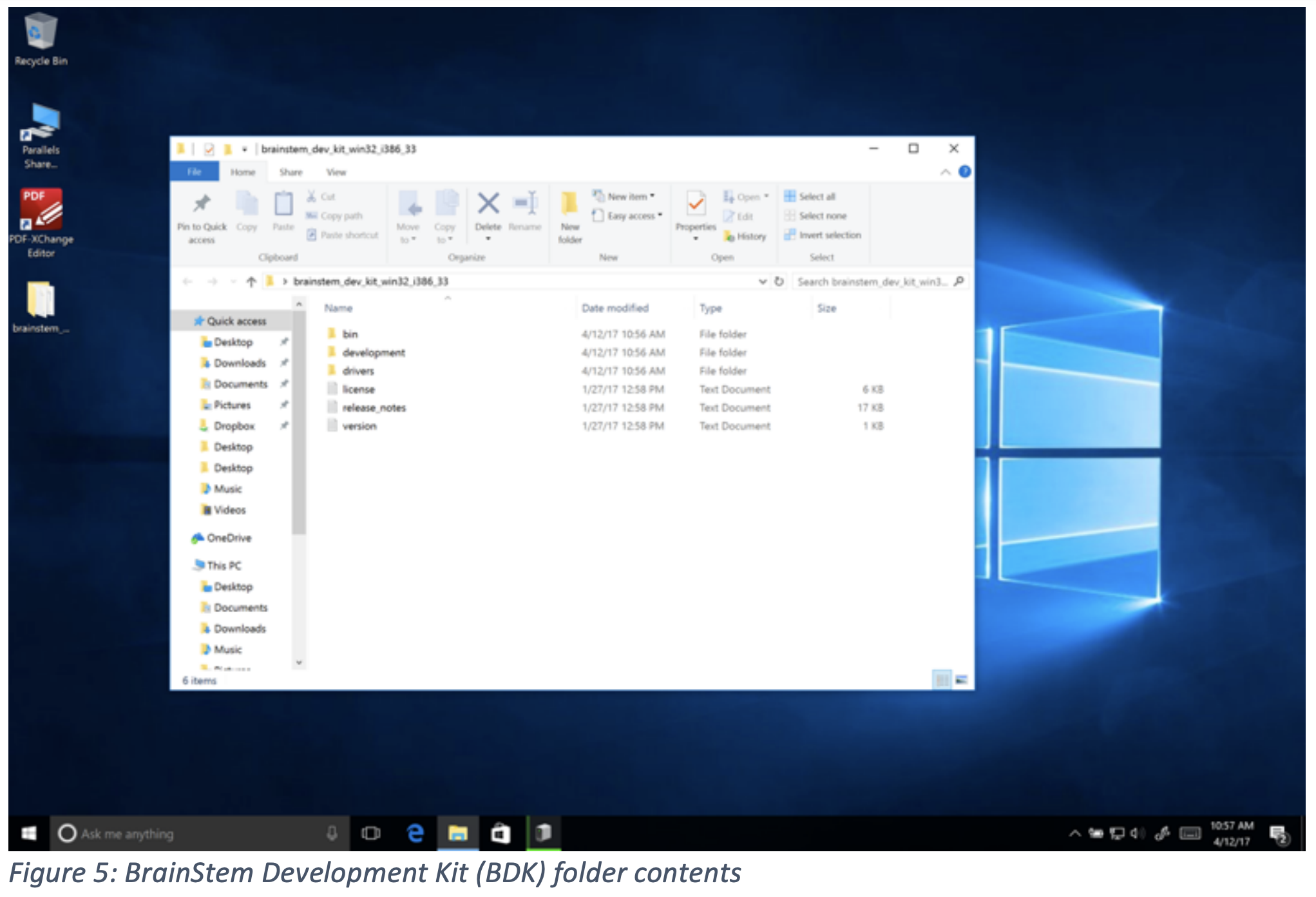
Expand the BDK package to a directory of your choosing. In this example, we have installed the BrainStem Development Kit for MS Windows to the local Desktop folder:
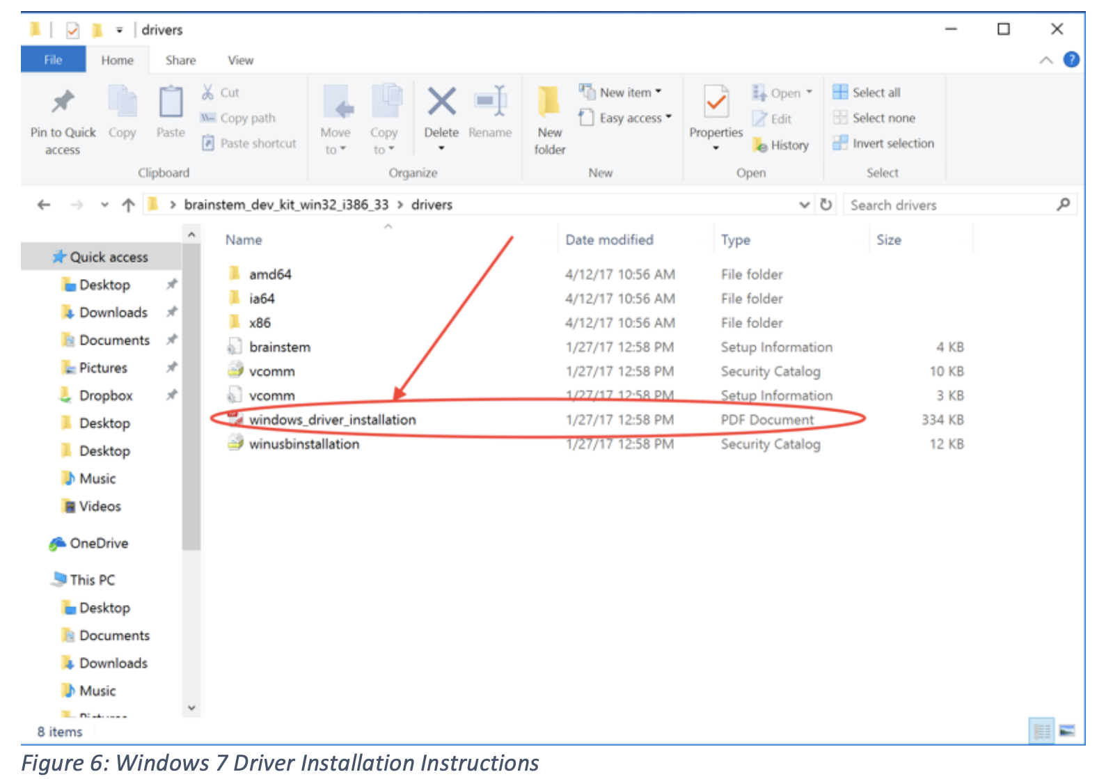
**Windows 7 CAVEAT** Under Windows 7, you will need to manually load the USB BrainStem driver. This applies only to Windows 7 and does not apply to Windows 8.1 or higher.
Instructions to update the BrainStem driver in Windows 7 are also included within the BDK directory under the \drivers folder:
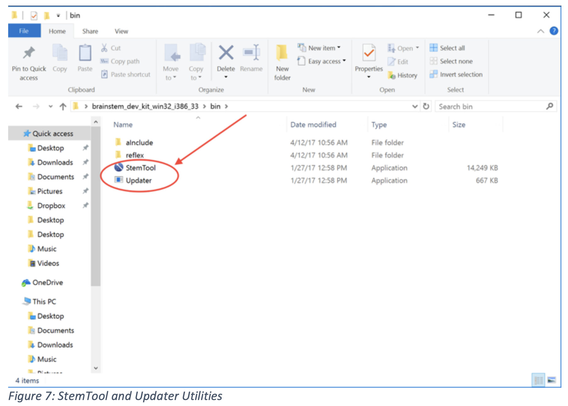
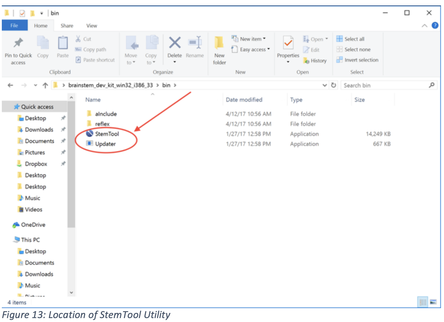
In the next steps of this guide, we will be using two applications, located in the /bin folder:
• Updater CLI/command line interface tool for updating and managing BrainStem firmware
• StemTool GUI tool used for exercising simple MTM module functions and troubleshooting

Firmware Update
Now that the BrainStem driver is loaded, update firmware on the BrainStem/MTM modules to the latest version.
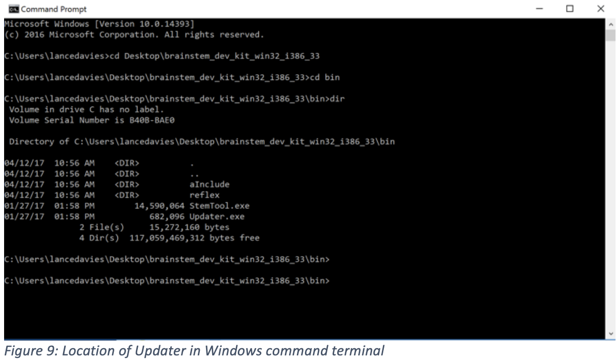
Navigate to the BDK directory and find the \bin folder where you will find the updater utility:
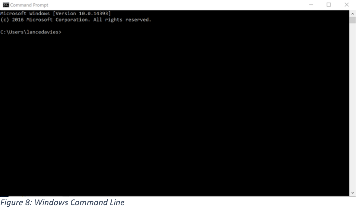
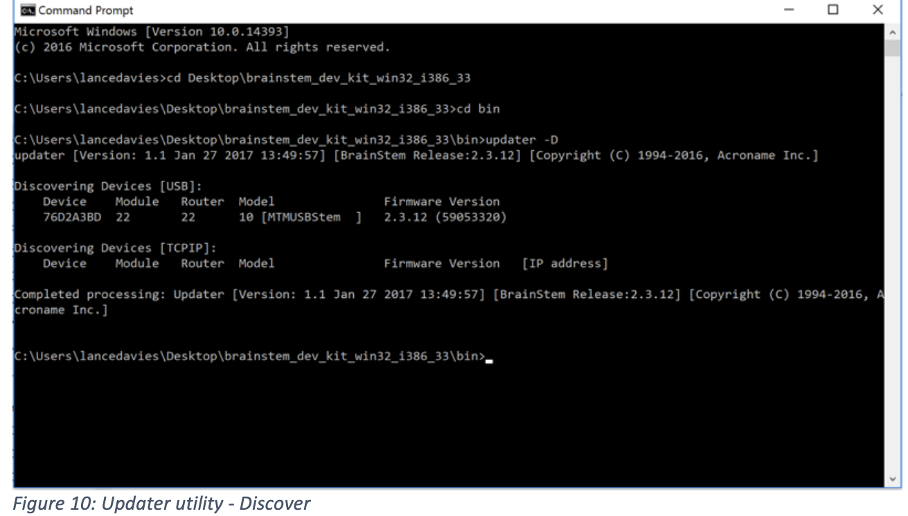
From the command line, run two separate commands to update firmware:
updater -D << this will Discover any locally attached BrainStem devices and return serial numbers in XXXXXXXX format >>
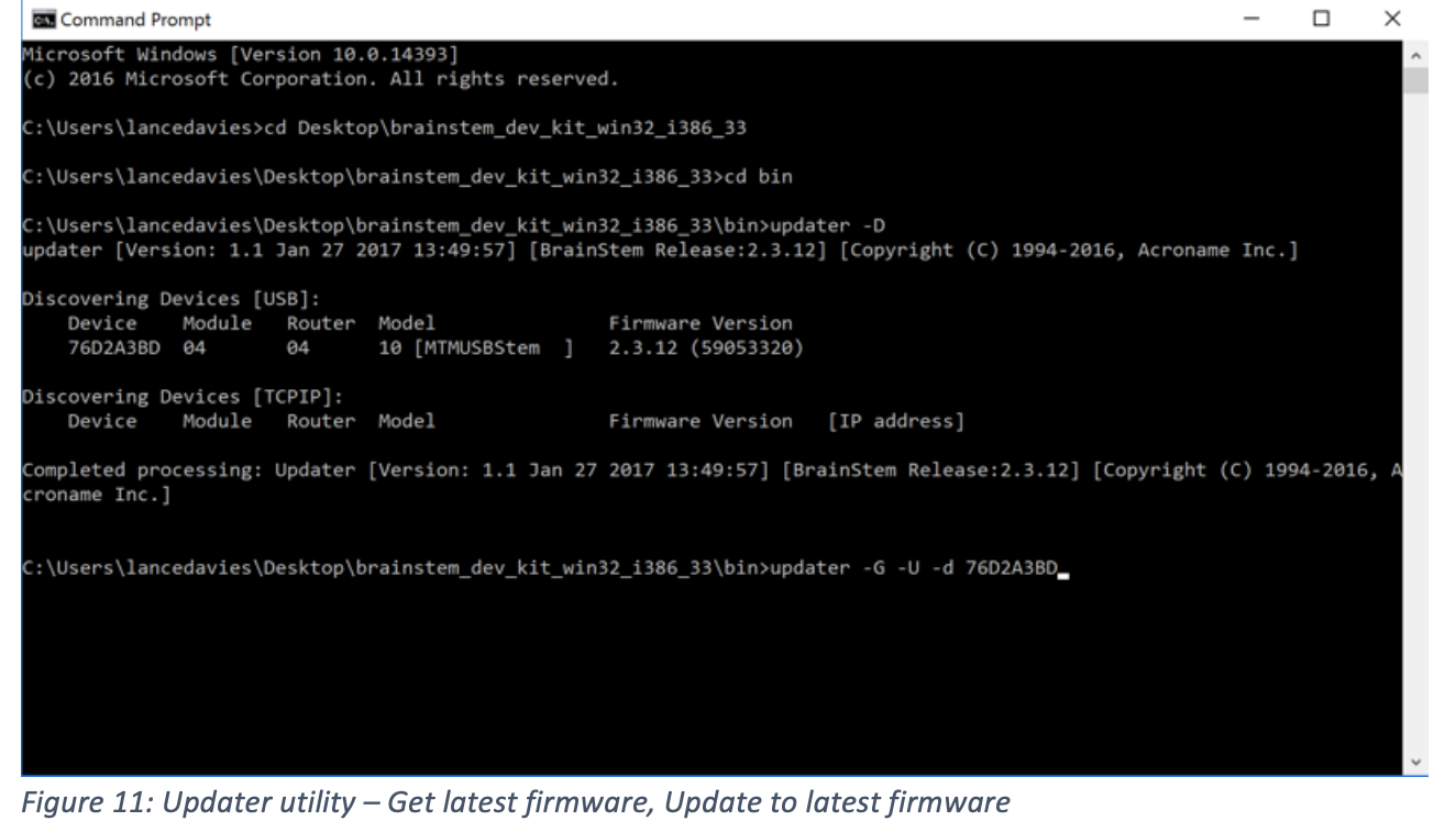
updater -G -U -d XXXXXXXX <<t his command will Get latest firmware from Acroname servers and Update the device with serial number XXXXXXXX >>
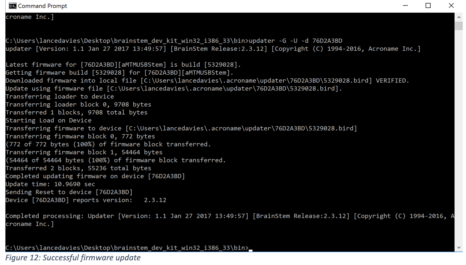
Once the updater utility successfully updates the module you are connected to, move the USB connection to the next module you would like to update and repeat the updater command sequence for each module.
In the future, with BrainStem networking enabled, you can update all modules without having to move the USB connection.
Exercising MTM Modules
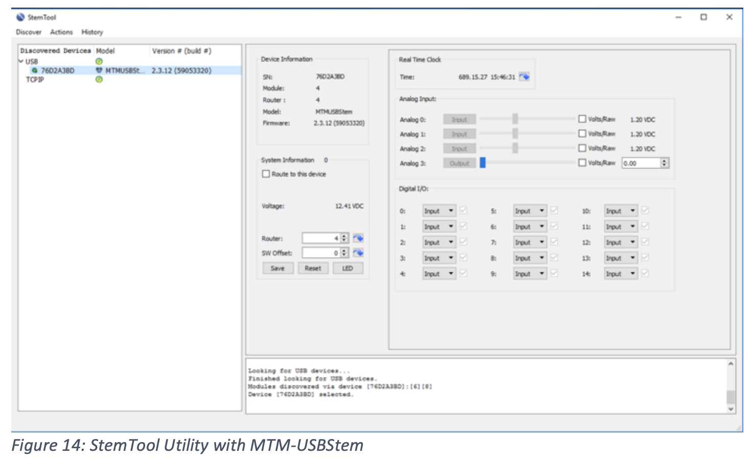
StemTool is a useful utility for exercising simple functions and generally troubleshooting MTM modules in the lab or in the field.
Start the StemTool GUI:
Open the BDK folder and navigate to the \bin directory. Double-click StemTool:
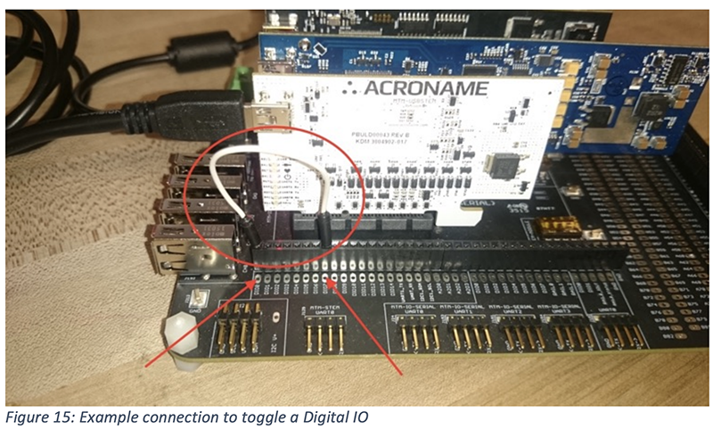
Exercise 1: Toggling a Digital IO
On the MTM Development board, connect a wire from one Digital pin to another digital pin. In this example, see the white jumper wire connecting D0 to D7 on the MTM-USBStem:
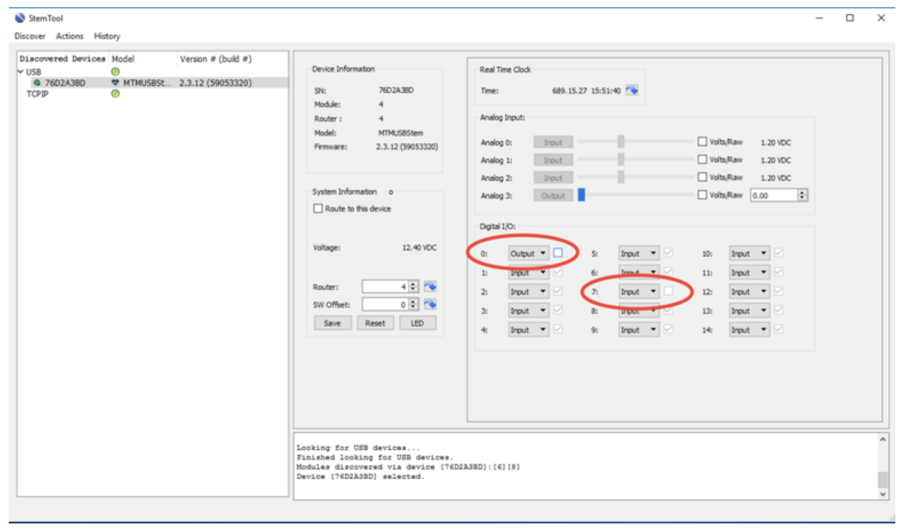
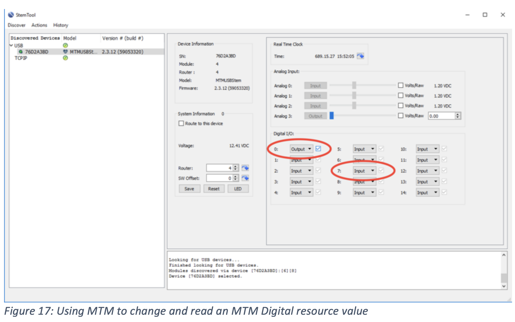
In StemTool, find the Digital I/O resource section. Change the configuration of the D0 resource from it’s default (input) to an output:
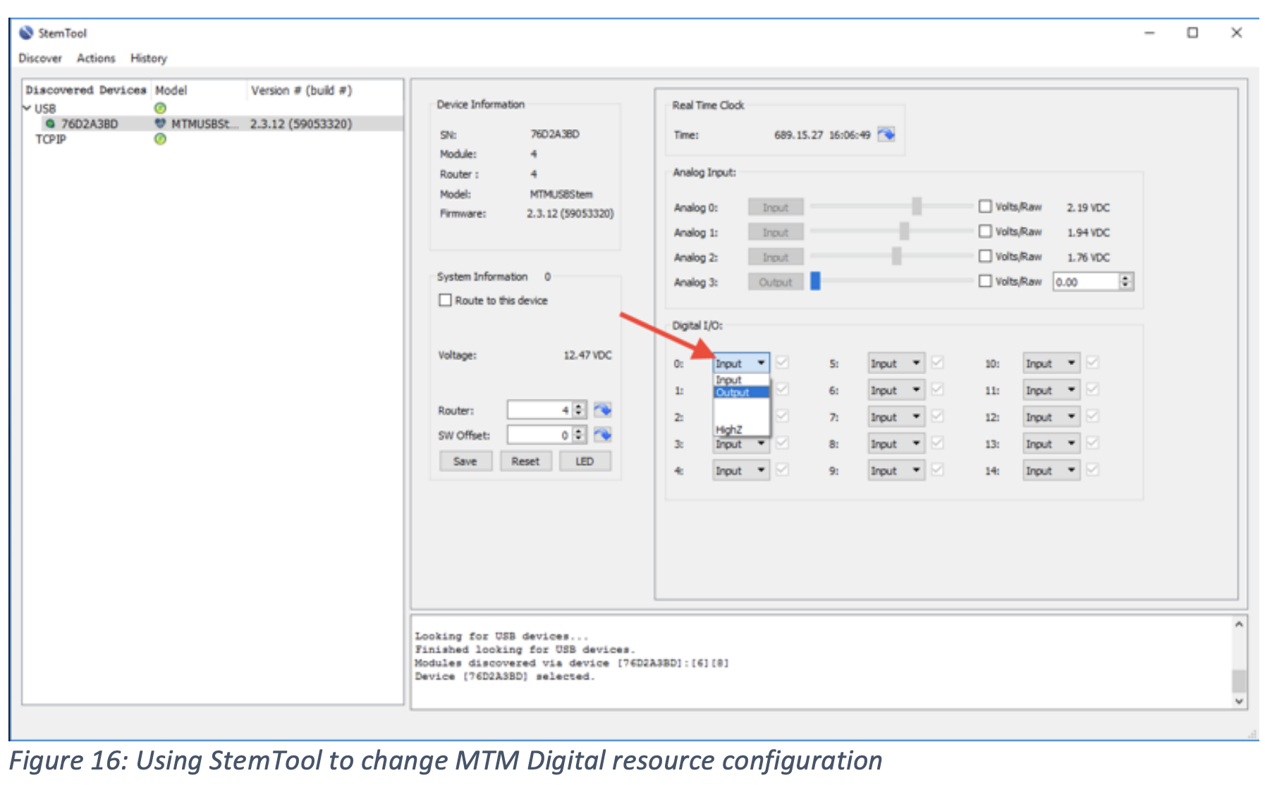
Toggling the checkbox next to the D0 output will change the logic level on D0. Since D0 is connected to D7, the D7 input logic level will change as indicated by the D7 checkbox:
Exercise 2: Measuring a voltage
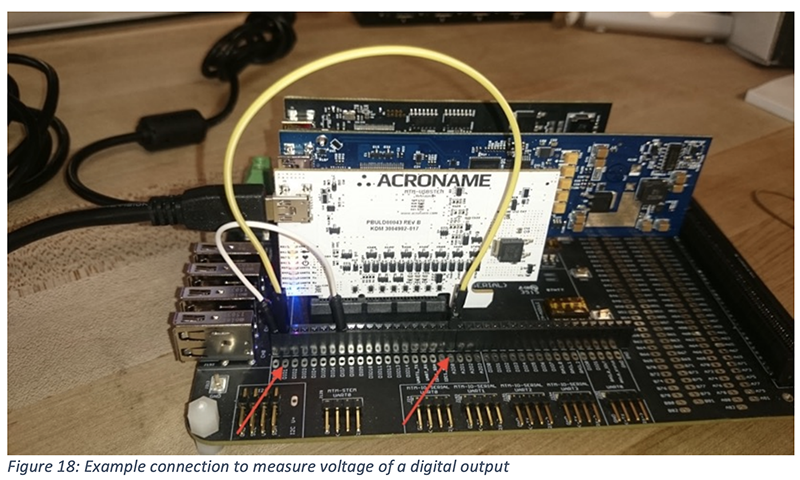
On the MTM Development board, connect a wire from one Digital pin to an Analog input pin. In this example, see the yellow jumper connecting D1 to AD0 on the MTM-USBStem:
In StemTool, find the Analog resource section and Digital I/O resource section. Change the configuration of the D1 resource from it’s default (input) to an output:
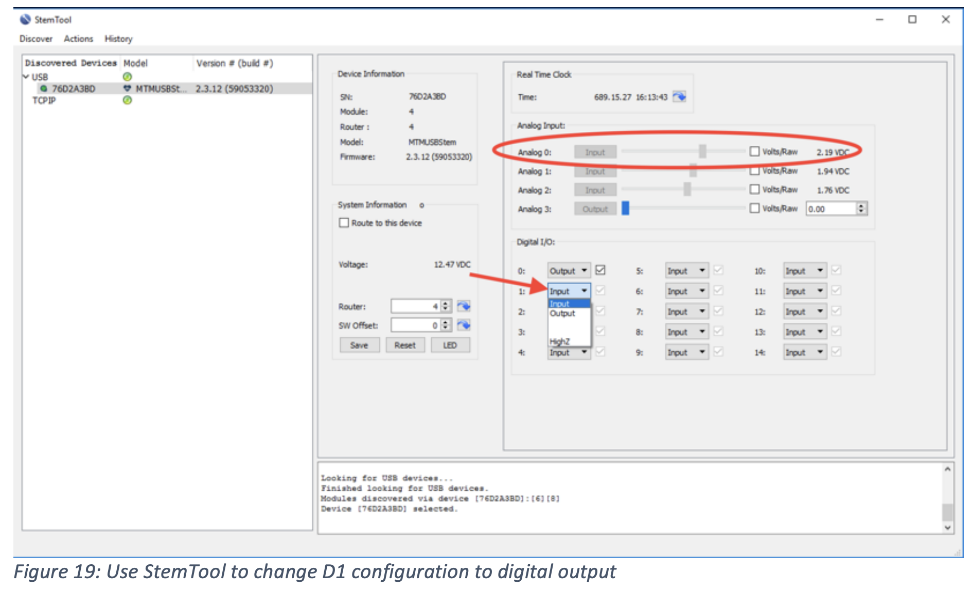
The A2D0 is now measuring the high logic level voltage on the D1 digital pin. Toggle the D1 output value box and you can see the A2D0 voltage measurement change:
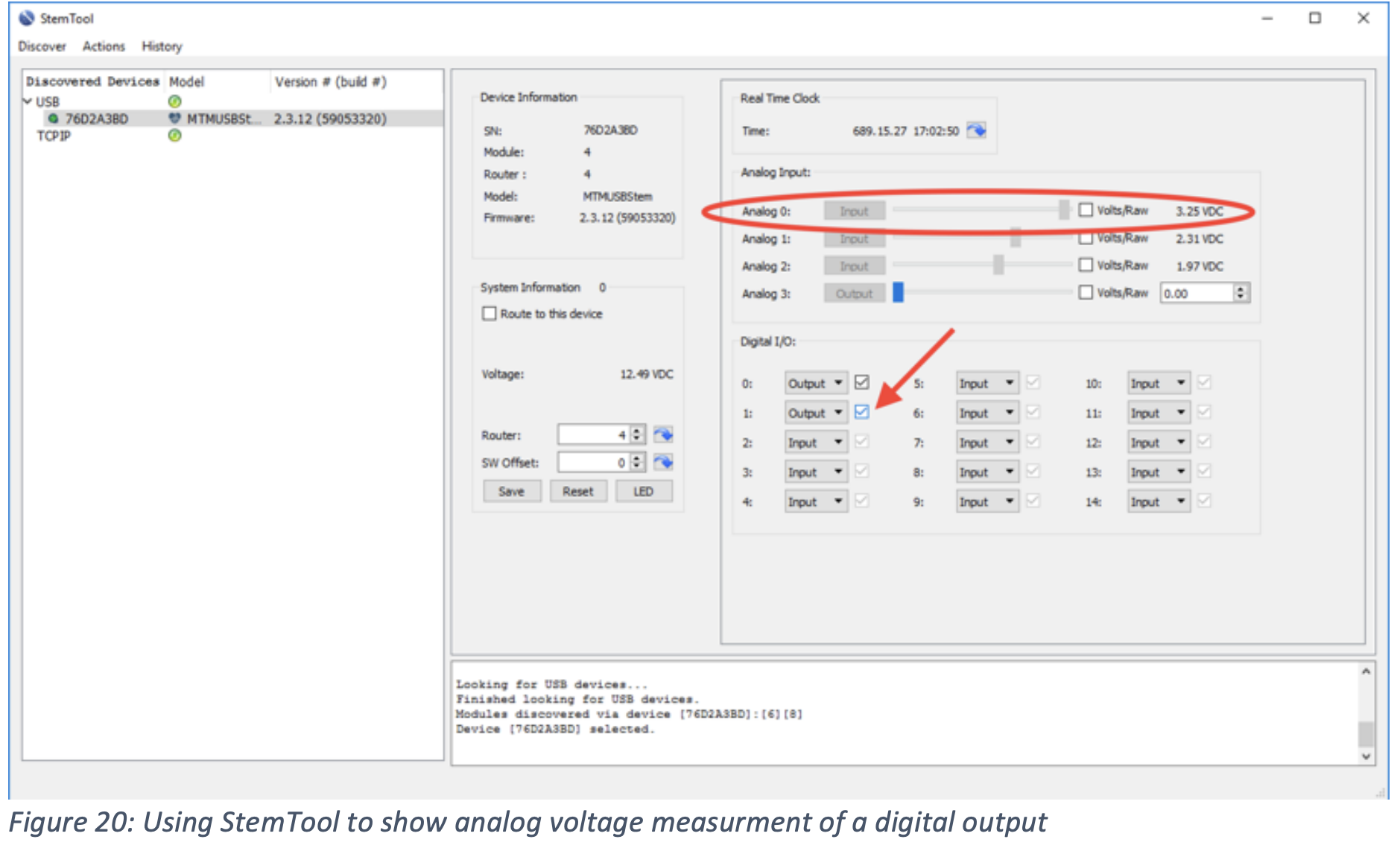
Since the A2D1 and A2D2 inputs are not connected to any signal, they are floating and their measurements indicate that case.
Exercise 3: Setting an analog output, measuring an analog voltage
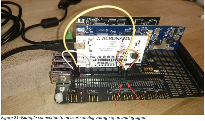
On the MTM Development board, connect a wire from an analog output to an analog input. In this example, see the red jumper wire connecting A2D3 (fixed configuration as an output) to the A2D1 input on the MTM-USBStem:
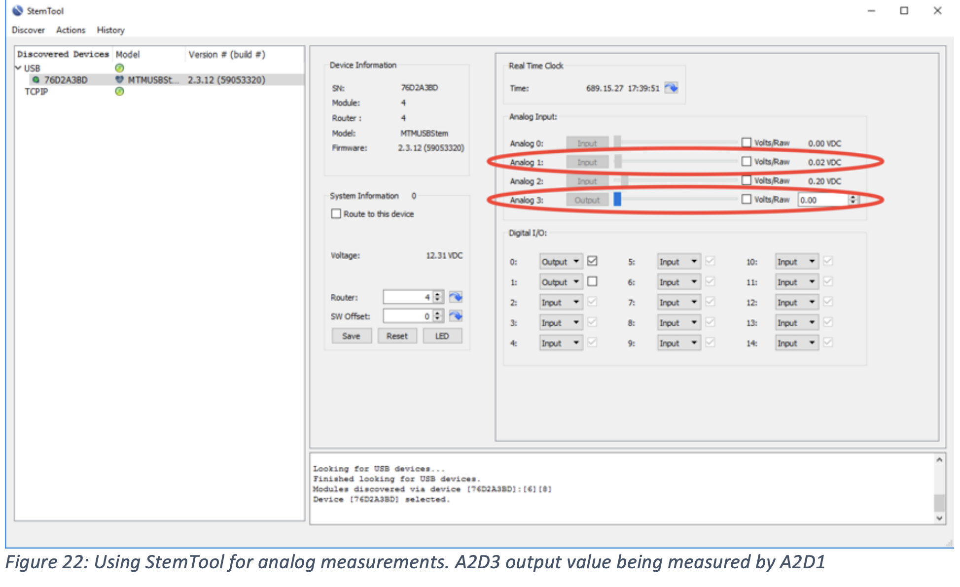
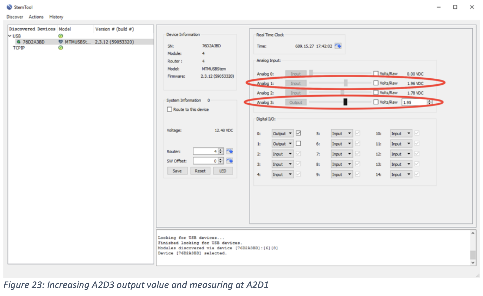
In StemTool, find the Analog resource section. Change the value of the A2D3 analog output by using the slider or the entry box. Note that the A2D1 value is affected and we can measure the analog voltage of the A2D3 output using the A2D1 input:
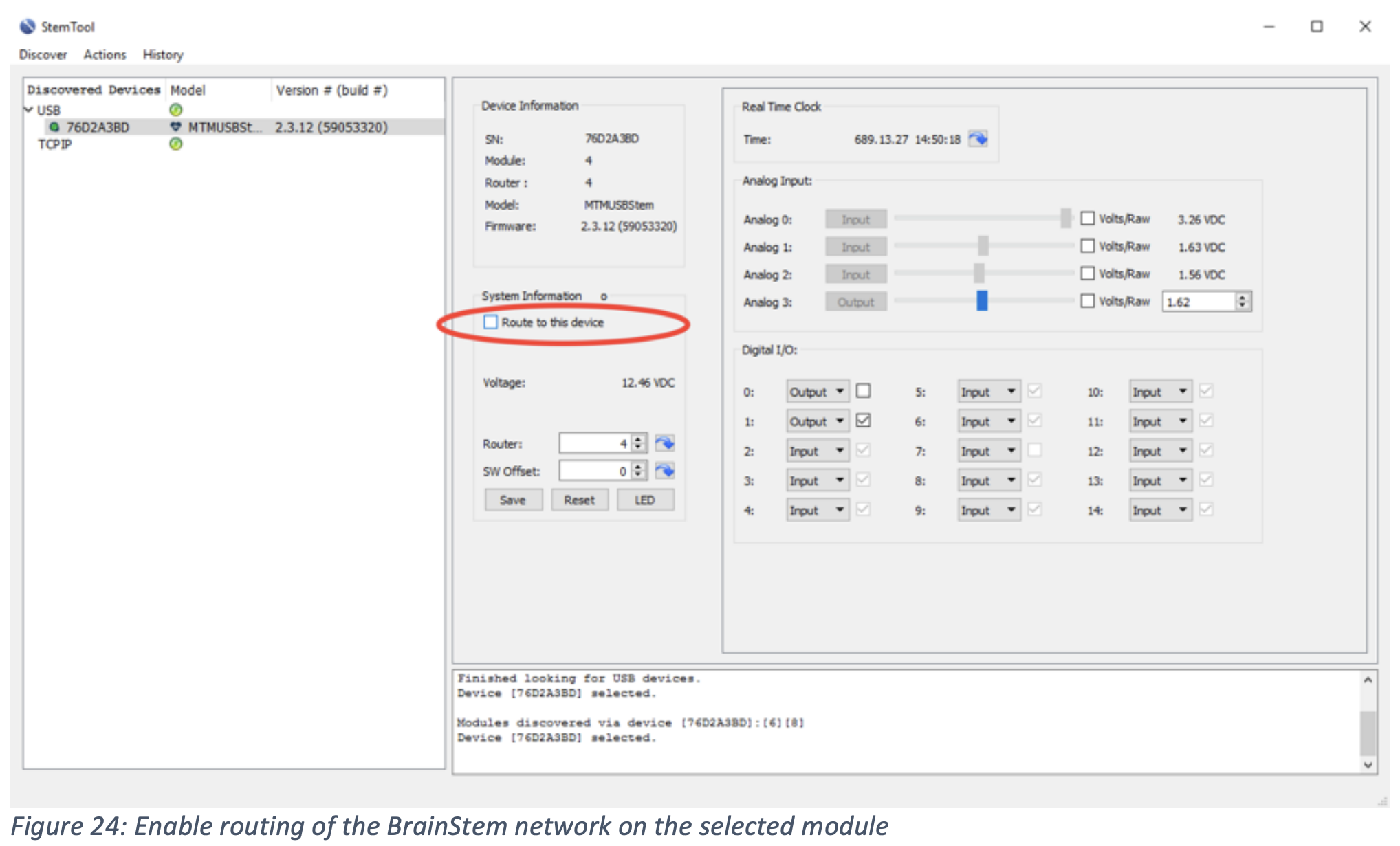
Exercise 4: Enabling Routing of a BrainStem Network
In a test environment, multiple MTM modules are usually present. The BrainStem network allows for a single host connection to one module to pass BrainStem commands and data to any other BrainStem-connected module. In this exercise, we will enable routing of a BrainStem network through the host-connected module. After doing so, we will then be able to access resources or update firmware on any networked modules – all using the same USB host connection. The BrainStem network will route commands appropriately between modules.
To enable the BrainStem network, use StemTool to enable the RouteToMe command. This will instruct the selected module to now be the parent or routing hub for all BrainStem network traffic. All attached modules are considered child modules in the BrainStem network:
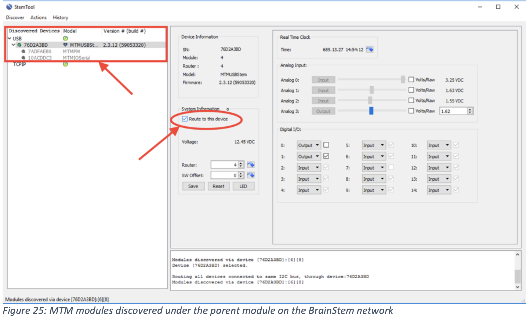
**NOTE** BrainStem routing settings of the parent and all child modules will remain until: (1) the RouteToMe function is disabled via StemTool, (2) the MTM Development Board is reset via button push or (3) a power cycle condition occurs.
With the BrainStem now enabled and routed through the parent MTM-USBStem, note the other which are now MTM modules accessible:
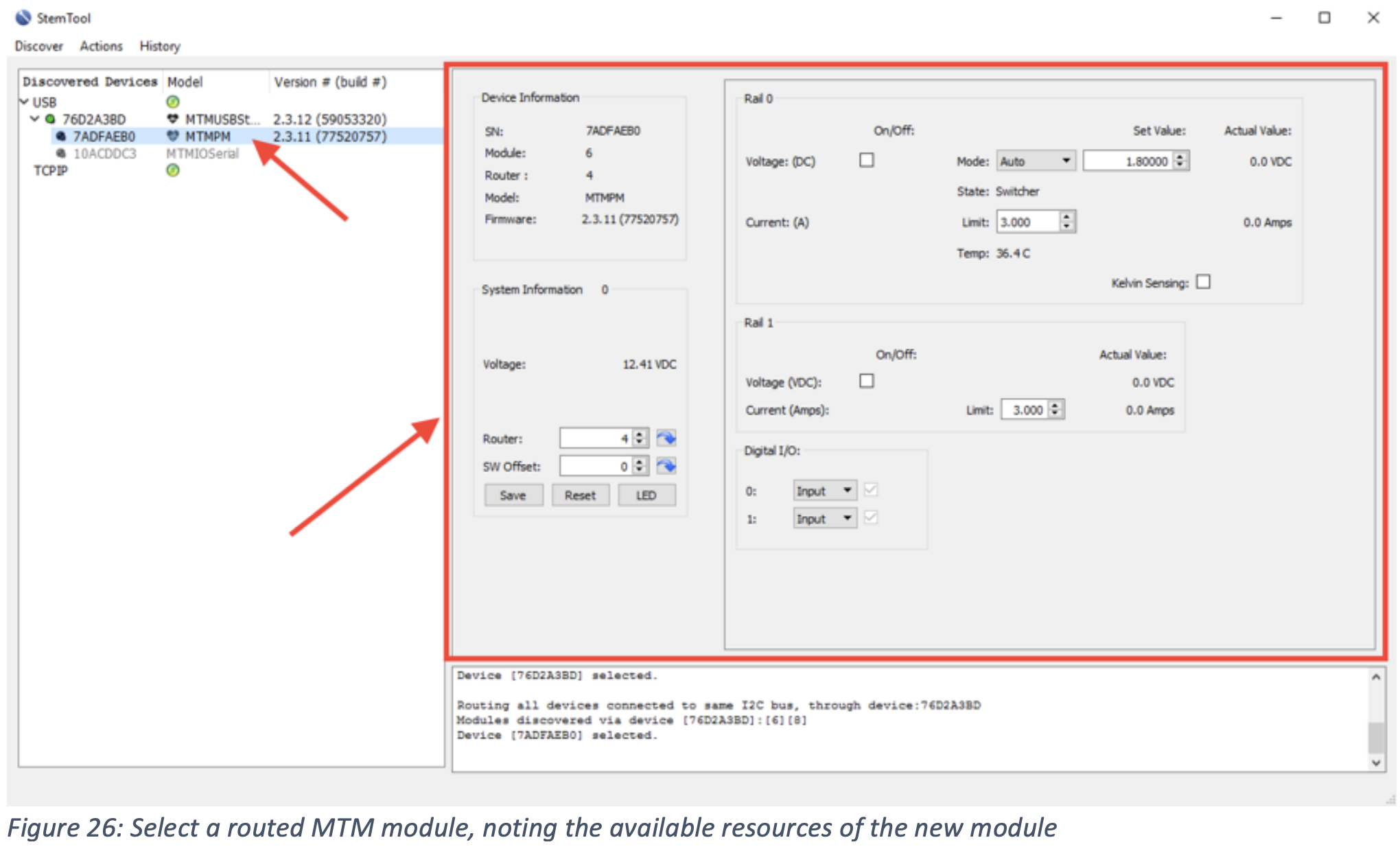
Select the MTM-PM-1 module. The BrainStem heartbeat icon should be enabled, indicating communication connection with that module. The function screen should also change to indicate the new functions of the selected module:
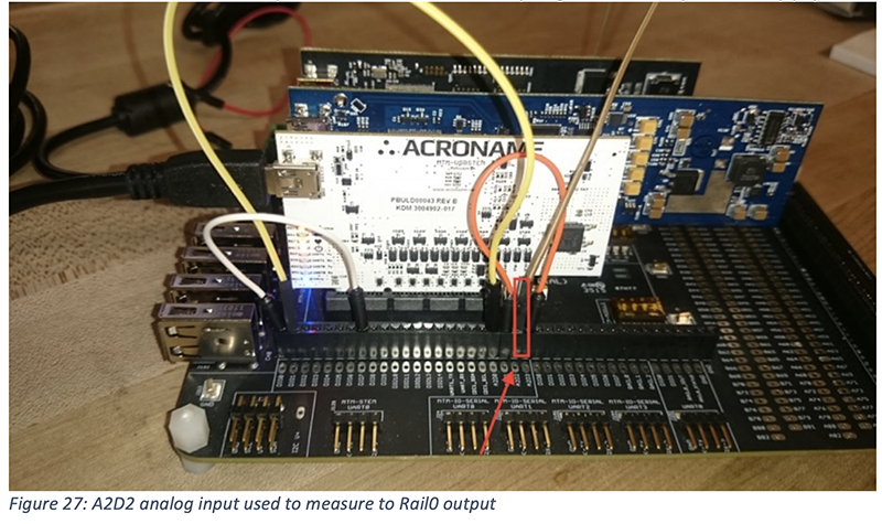
Exercise 5: Using multiple MTM Modules - Analog Measurement of a Power Rail
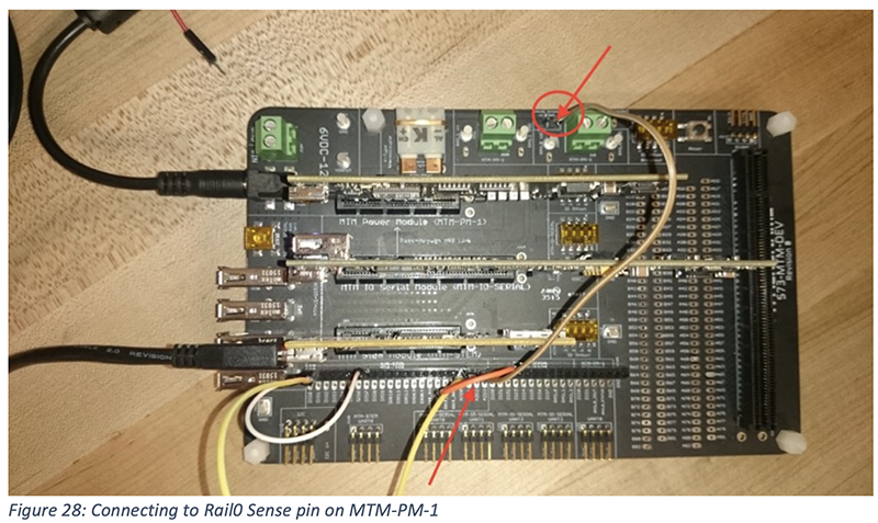
On the MTM Development board, connect a wire from a power rail to an available analog input. In this example, see the brown jumper wire connecting A2D2 (analog input) of the MTMUSBStem to the Rail0 output on the MTM-PM-1 programmable power supply:
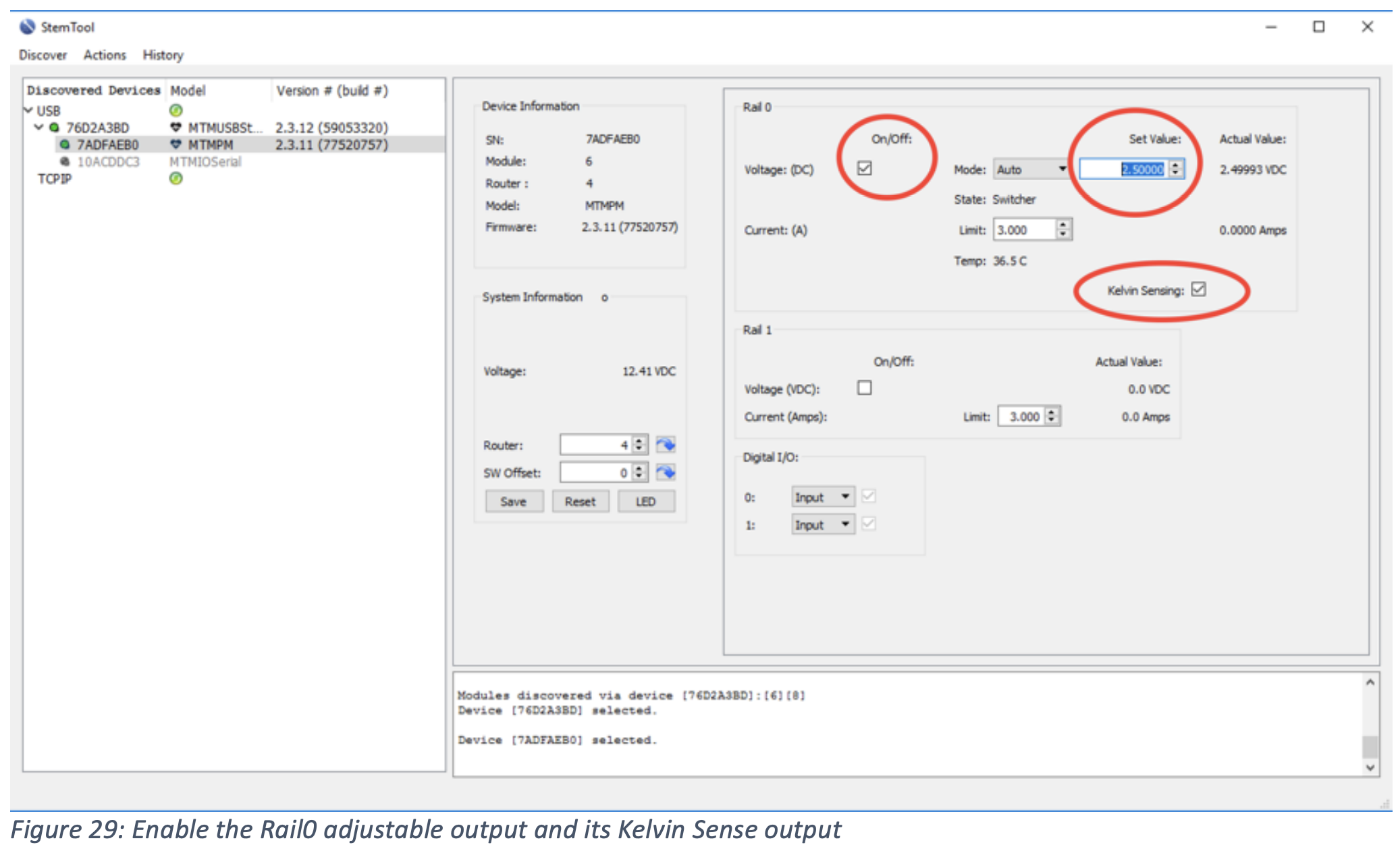
Enable the adjustable Rail0 output and Kelvin Sense output and set the Rail0 voltage to a level you wish to measure. We have chosen 2.5V for this example:
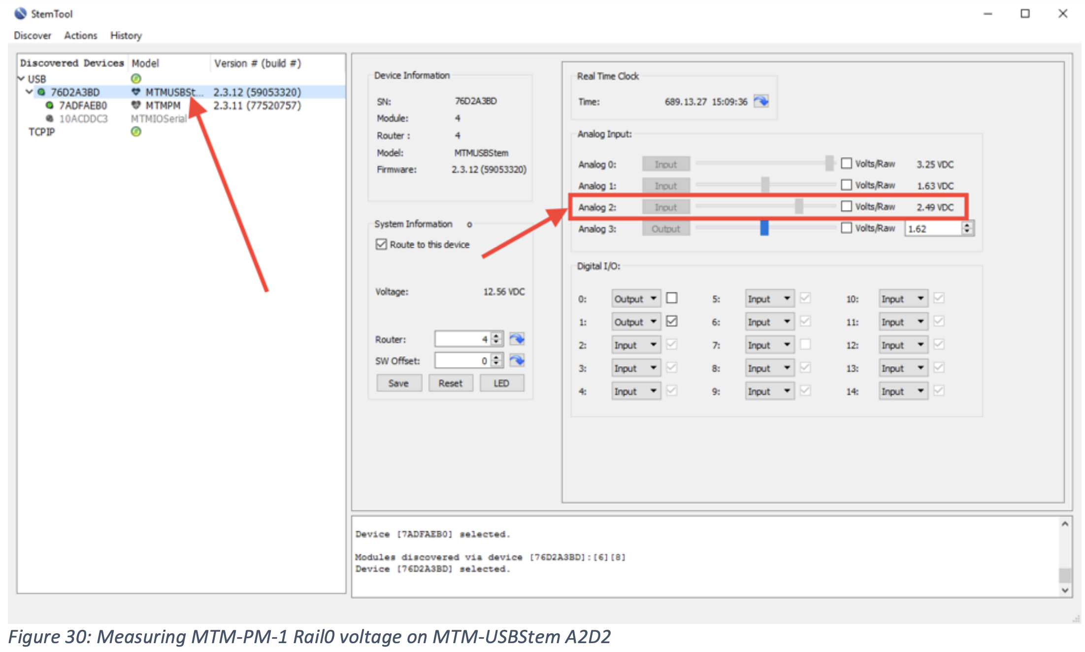
Return to the MTM-USBStem module and note that A2D2 is now measuring the previously set voltage enabled on MTM-PM-1 Rail0:
Congratulations! You are now fully up and running with MTM instrumentation!
As a next step, you can implement your test plan using the BrainStem APIs and design a lowcost fixture that integrates MTM instrumentation.
Please see our blog (www.acroname.com/blog) for latest updates and video tours of our instrumentation and other manufacturing test tools.
If you have any questions, concerns or comments, please contact us at:
Acroname Sales (sales@acroname.com) or Acroname Support (support@acroname.com)