
MTM Application Notes
Specific use cases and implementation for MTM
Make the most of MTM
AN1: LED Test (V/I)
Verify LED presence, orientation and type with voltage and current measurements.
Title: LED Test Application Note
Document No.: 1
Prepared By: James Dudley
Prepared Date: February 26, 2018
A common goal in manufacturing tests is to verify that LEDs were placed correctly during assembly and are electrically functional. Although LEDs are optical indicators, there are two simple ways of verifying correct placement without expensive or error-prone optical tests: measuring and verifying the forward voltage drop across the LED, and measuring and verifying the current through the LED. In both cases, the measured value can be compared directly to an expected value — if the LED is improperly placed, or absent entirely, the values will not match.
In this application note, we will demonstrate basic voltage and current measurement tests using the MTM-DAQ-1 analog IO module
Components used:
- x1 S84-MTM-DAQ-1
- x1 S73-MTM-DEV, with extra module connector installed
- x1 Through-hole LED
- x1 500Ω through-hole resistor
- x1 12V/5A Power Adapter
- x1 USB Type A to mini-B Cable
- Breadboard and Standard Jumper Wires
- PC with BrainStem API
Hardware Setup:
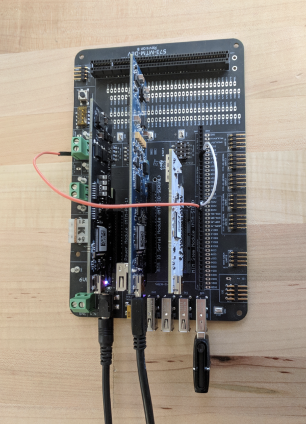
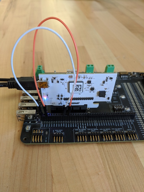
First, set up the development board. Place the MTM-DAQ-1 board in the extra module connector. Power the development board using the 12V power adapter. Connect the USB cable between your host PC and the MTM-DAQ-1.
Next, build the simple LED circuit (see Schematic and Hardware). Connect the resistor from Position A (PWR) to Position B, the LED anode to Position B, and the cathode to Position C (GND)
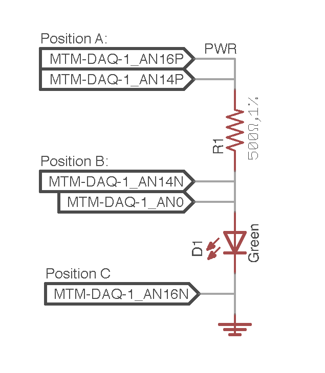
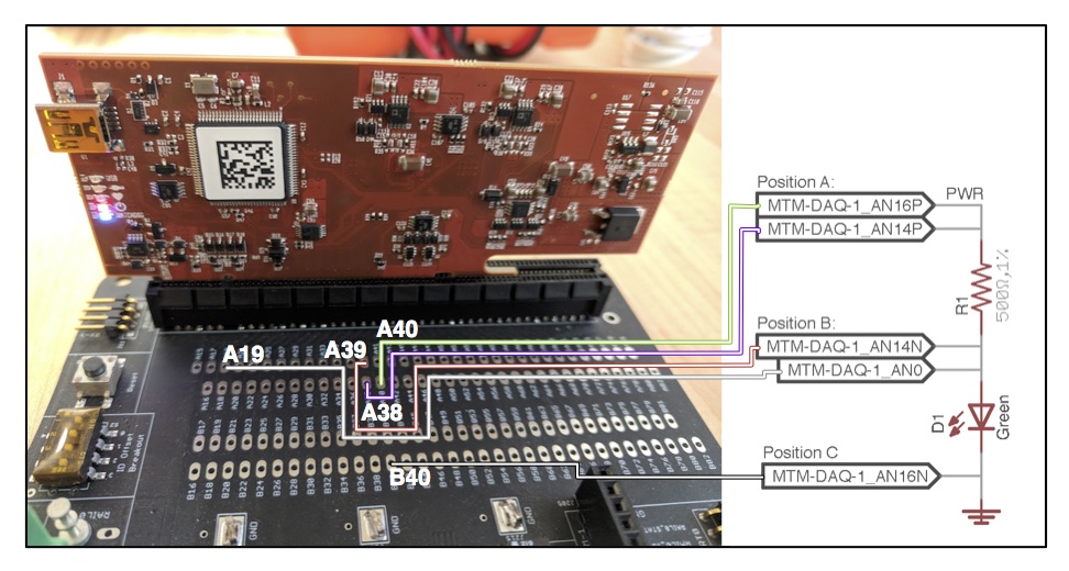
Make the relevant connections between the development board and breadboard:
- MTM-DAQ-1 AN16P (A40) to Position A
- MTM-DAQ-1 AN14P (A38) to Position A
- MTM-DAQ-1 AN14N (A39) to Position B
- MTM-DAQ-1 AN0 (A19) to Position B
- MTM-DAQ-1 AN16N (B40) to Position C
Software Setup (Python):
Make sure your PC has the BrainStem API wheel installed, then download the example file.
Python File download link
Running the Test (Python):
Open a terminal and navigate to the location of the example file.
>> python mtm_led_test.py
Software Setup (C++):
Make sure your PC has the BrainStem API downloaded, then download the example file and substitute it into the "BrainStem2-Cpp-example" project.
C++ File download link
Running the Test (C++):
Follow the Cpp-example How_To_Build.txt instructions with mtm_led_test.cpp substituted for main.cpp.
Interpreting the Results:
The output will show Voltage and Current measurements. Compare these values to the expected values. The expected voltage measurement is the forward diode drop of the LED, the expected current measurement is the LED current draw, and both can be found in the datasheet of your LED. If the values are within a certain range (say, +/- 100mV and +/- 5mA), the LED is present and functioning correctly.
Try removing the LED from the circuit and running the program again. Try reversing the LED. Notice how the measured values change and can be used to tell whether the LED is placed correctly and electrically functioning
AN2: BrainStem Networking
Create an MTM network to control a variety of MTM functionality from a single host (USB) connection.
Title: BrainStem Networking Application Note
Document No.: 2
Prepared By: James Dudley
Prepared Date: March 12, 2018
Many test applications require features from more than one MTM board. For instance, your test fixture may require programmable DUT power from the MTM-PM-1, USB control from MTM-IO-SERIAL, and an expanded number of DIO from the MTM-USBSTEM. MTM is designed to provide easy networking between modules, allowing access to all of these capabilities from a single USB host connection. This minimizes cable clutter and makes changing out modules on your automated test system simple.
In this application note, we will use a BrainStem network to access all of the features on MTM-IO-SERIAL, MTM-PM-1, and MTM-USBSTEM boards from a single USB host connection
Components used:
- x1 S48-MTM-PM-1
- x1 S62-MTM-IO-SERIAL
- x1 S69-MTM-USBSTEM
- x1 S73-MTM-DEV
- x1 self-powered USB device (optional)
- x1 12V/5A Power Adapter
- x1 USB Type A to mini-B Cable
- Breadboard and Standard Jumper Wires
- PC with BrainStem API
Hardware Setup:
First, set up the development board. Place each of the three MTM modules in their respective module connectors. Power the development board using the 12V power adapter. Connect the USB cable between your host PC and the MTM-IO-SERIAL.
Next, make the following connections:
- MTM-PM-1 RAIL0 V+ (screw terminal) to MTM-STEM A2D0
- MTM-IO-SERIAL RAIL1 (0.1" header) to MTM-STEM A2D1
- (optional) USB device plugged into MTM-IO-SERIAL CH0
Software Setup (Python):
Make sure your PC has the BrainStem API wheel installed, then download the example file.
Python File download link
Running the Example (Python):
Open a terminal and navigate to the location of the example file.
>> python mtm_brainstem_network.py
When prompted verify USB device enumeration (optional) and press Enter to continue.
Software Setup (C++):
Make sure your PC has the BrainStem API downloaded, then download the example file and substitute it into the "BrainStem2-Cpp-example" project.
C++ File download link
Running the Example (C++):
Follow the Cpp-example How_To_Build.txt instructions with the mtm_brainstem_network.cpp substituted for main.cpp.
When prompted verify USB device enumeration (optional) and press Enter to continue.
Interpreting the Results:
The output will show Voltage and Current measurements. Compare these values to the expected values. The expected voltage measurement is the forward diode drop of the LED, and the expected current measurement is the LED current draw — both of which can be found in the datasheet of your LED. If the values are within a certain range (say, +/- 100mV and +/- 5mA), the LED is present and functioning correctly.
Try removing the LED from the circuit and running the program again. Try reversing the LED. Notice how the measured values change and can be used to tell whether the LED is placed correctly and electrically functioning
AN3: Continuity Test
Test point-to-point signal continuity with MTM-USBSTEM.
Title: Continuity Test Application Note
Document No.: 3
Prepared By: James Dudley
Prepared Date: March 5, 2018
Testing electrical continuity between two points is simple with MTM digital IO, but several configurations must be correctly applied.
In this application note, we will demonstrate continuity tests using the MTM-USBStem module
Components used:
- x1 S69-MTM-USBSTEM
- x1 S73-MTM-DEV, with extra module connector installed
- x1 12V/5A Power Adapter
- x1 USB Type A to mini-B Cable
- Standard Jumper Wires
- PC with BrainStem API
Hardware Setup:
First, set up the development board. Place the MTM-USBSTEM board in the MTM Stem Module connector. Power the development board using the 12V power adapter. Connect the USB cable between your host PC and the MTM-USBSTEM.
Next, create the connections we'll be testing. Make the following connections in the 0.1" header for MTM-STEM:DIO0 -- DIO9
DIO2 -- DIO 11
We'll leave the following digital IO pairs unconnected to illustrate discontinuity:
DIO1 -- DIO10
DIO3 -- DIO12
DIO5 -- DIO14
DIO4 -- DIO 13
Software Setup (Python):
Make sure your PC has the BrainStem API wheel installed, then download the example file.
Python File download link
Running the Test (Python):
Open a terminal and navigate to the location of the example file.
>> python mtm_continuity_test.py
Software Setup (C++):
Make sure your PC has the BrainStem API downloaded, then download the example file and substitute it into the "BrainStem2-Cpp-example" project.
C++ File download link
Running the Test (C++):
Follow the Cpp-example How_To_Build.txt instructions with the mtm_continuity_test.cpp substituted for main.cpp.
Interpreting the Results:
The output will show continuity or lack thereof between the 5 DIO pairs specified earlier. Compare these results to the actual connections made by jumper wires. The lower-numbered digital IO are configured as Outputs (configuration value 1), and the higher-numbered DIO are configured as Inputs with pull-down resistor (configuration value 5).
After running the test for the first time, note the continuity results. Try changing the jumper wire connections and re-running the test.
Note: the default test script configures DIO0-8 as outputs and DIO9-14 as inputs with pull-down. One of each configuration, with the output used to toggle state, is required for a continuity test
AN4: DUT Power Short Protection
Power your DUT with a short-protected power rail on MTM-PM-1.
Title: DUT Power Short Protection Application Note
Document No.: 4
Prepared By: James Dudley
Prepared Date: March 2, 2018
One of the most critical aspects of a functional test (FCT) fixture is the ability to properly handle a shorted device under test (DUT). If handled incorrectly, such a short can cause damage to the DUT, expensive test equipment, or both. In the MTM line, the MTM-PM-1 is specifically designed to provide reliable, protected, programmable power rails for FCT/ICT.
In this application note, we will demonstrate basic DUT power and short protection using the MTM-PM-1 programmable power supply module
Components used:
- x1 S48-MTM-PM-1
- x1 S73-MTM-DEV
- x1 12V/5A Power Adapter
- x1 USB Type A to mini-B Cable
- Standard Jumper Wires
- PC with BrainStem API
- (optional) Digital Multimeter
Hardware Setup:
First, set up the development board. Place the MTM-PM-1 board in the MTM Power Module connector. Power the development board using the 12V power adapter. Connect the USB cable between your host PC and the MTM-PM-1.
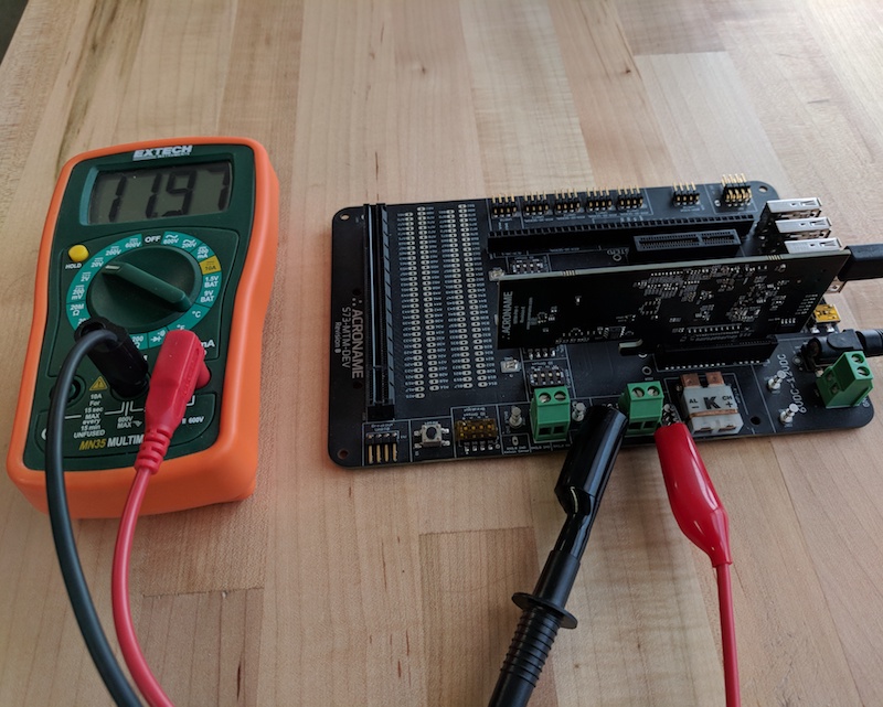
(Optional) Connect the multimeter to the MTM-PM-1 Rail 1 post connectors and set it to read up to 15VDC
Software Setup (Python):
Make sure your PC has the BrainStem API wheel installed, then download the example file.
Python File download link
Running the Test (Python):
Open a terminal and navigate to the location of the example file.
>> python mtm_short_test.py
As the test runs, note the "Enable State" of the rail, printed to the terminal. It will go to ON (1) for several seconds before returning to OFF (0).
If you used a multimeter (optional), note the reported voltage. This value should go up to ~12V for several seconds before turning off.
Now, use a jumper wire to connect the RAIL1 V+ to RAIL1 GND - you can use the screw terminal, through-hole pads, or posts. This creates a short in the power line, and we'll see how the MTM-PM-1 handles it.
Re-run the test. Note how the "Enable State" stays OFF (0) and the multimeter (optional) remains at 0V.
Software Setup (C++):
Make sure your PC has the BrainStem API downloaded, then download the example file and substitute it into the "BrainStem2-Cpp-example" project.
C++ File download link
Running the Test (C++):
Follow the Cpp-example How_To_Build.txt instructions with mtm_short_test.cpp substituted for main.cpp.
As the test runs, note the "Enable State" of the rail, printed to the terminal. It will go to ON (1) for several seconds before returning to OFF (0).
If you used a multimeter (optional), note the reported voltage. This value should go up to ~12V for several seconds before turning off.
Now, use a jumper wire to connect the RAIL1 V+ to RAIL1 GND - you can use the screw terminal, through-hole pads, or posts. This creates a short in the power line, and we'll see how the MTM-PM-1 handles it.
Re-run the test. Note how the "Enable State" stays OFF (0) and the multimeter (optional) remains at 0V.
Interpreting the Results:
The output will show Enable State and Voltage measurements. In the first test, with no short, the Enable State will remain ON (1) for the several second window built into the test. The multimeter (optional) will read approximately 12V, which is the voltage level of the power adapter passed through Rail 1 of the MTM-PM-1.
In the second test, with a power-to-GND short, the Enable State will remain OFF (0). The multimeter (optional) will read 0V, which reflects the disabled state of the rail. Rail 1 of the MTM-PM-1 will automatically disable itself immediately upon an over-current event, which a short will cause, and not re-enable until specifically commanded to do so.
To test the over-current limit, try modifying the defined current limit in the test script and using a power resistor to drive different currents through Rail 1.
MAKE SURE TO USE A SUFFICIENTLY HIGH-WATTAGE RESISTOR. For example:
V = 12V, R = 10Ω, I = 12/10 = 1.2A; P = I * V = 1.2 * 12 = 14.4W
You can also try shorting the rail output partway through the test. Note the rail voltage read by the API still shows the same ~12V. This is because the rail voltage measurement is taken inside the enable/disable circuit, providing a means of viewing the rail voltage without enabling the rail. The multimeter (optional) will show 0V after the short.