Acroname’s USB-C-Switch is an industrial USB-C switch able to connect one of up to four devices to a host, or one device to one of up to four hosts. It is not a hub – the selected ports form a bidirectional connection and appear “like a cable” to connected devices, even supporting USB alt modes like DisplayPort.
When combined with an Acroname Universal Orientation Cable , the USB-C-Switch can emulate a cable flip, allowing tests of all the connections on a port without the need to manually flip the cable.
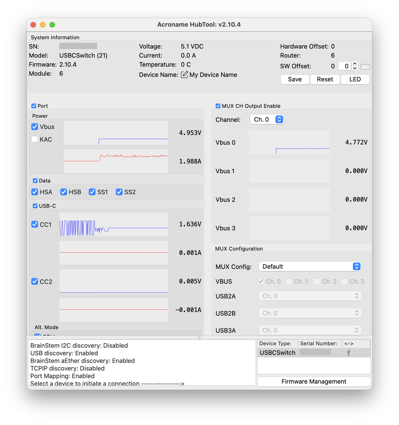
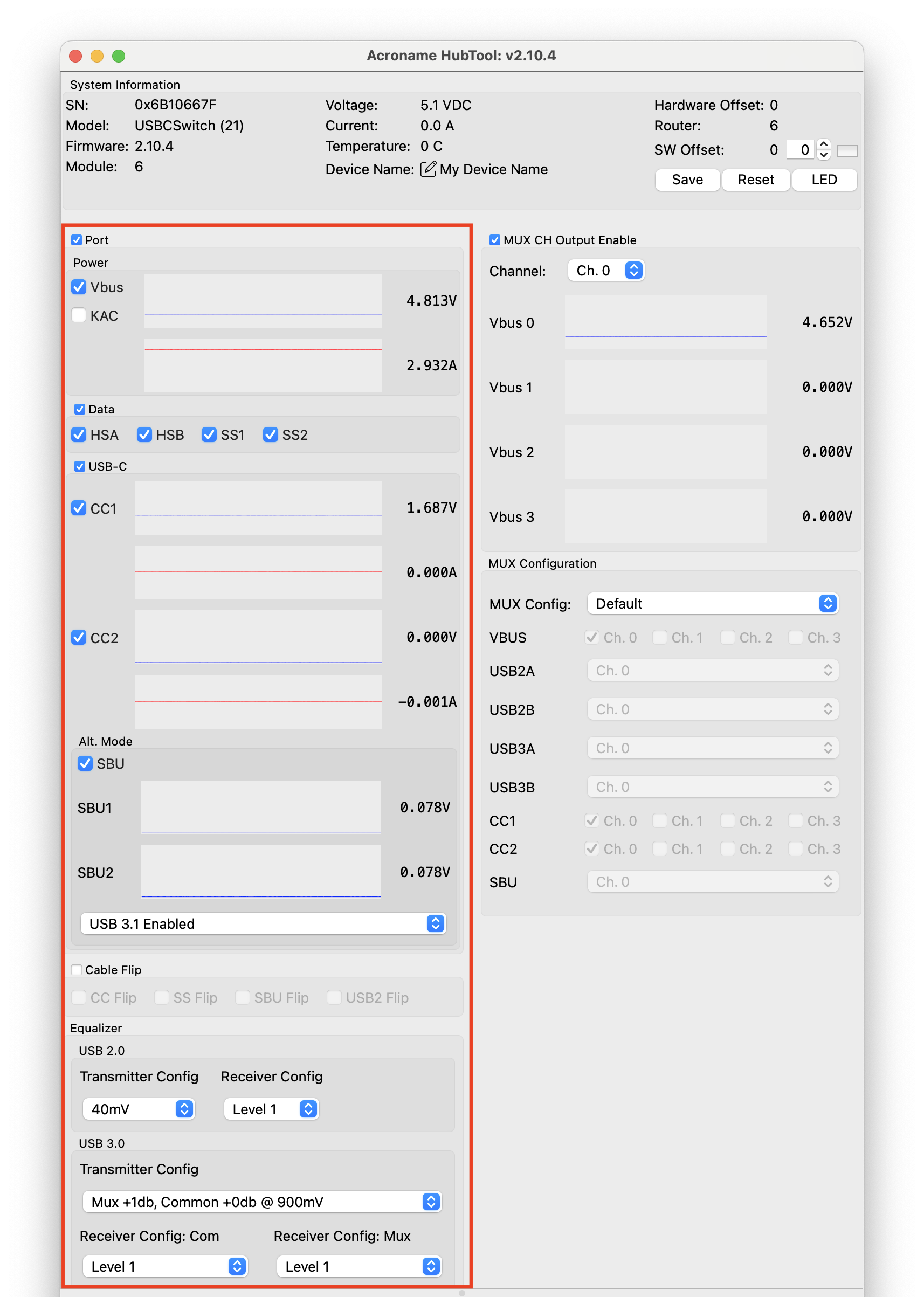
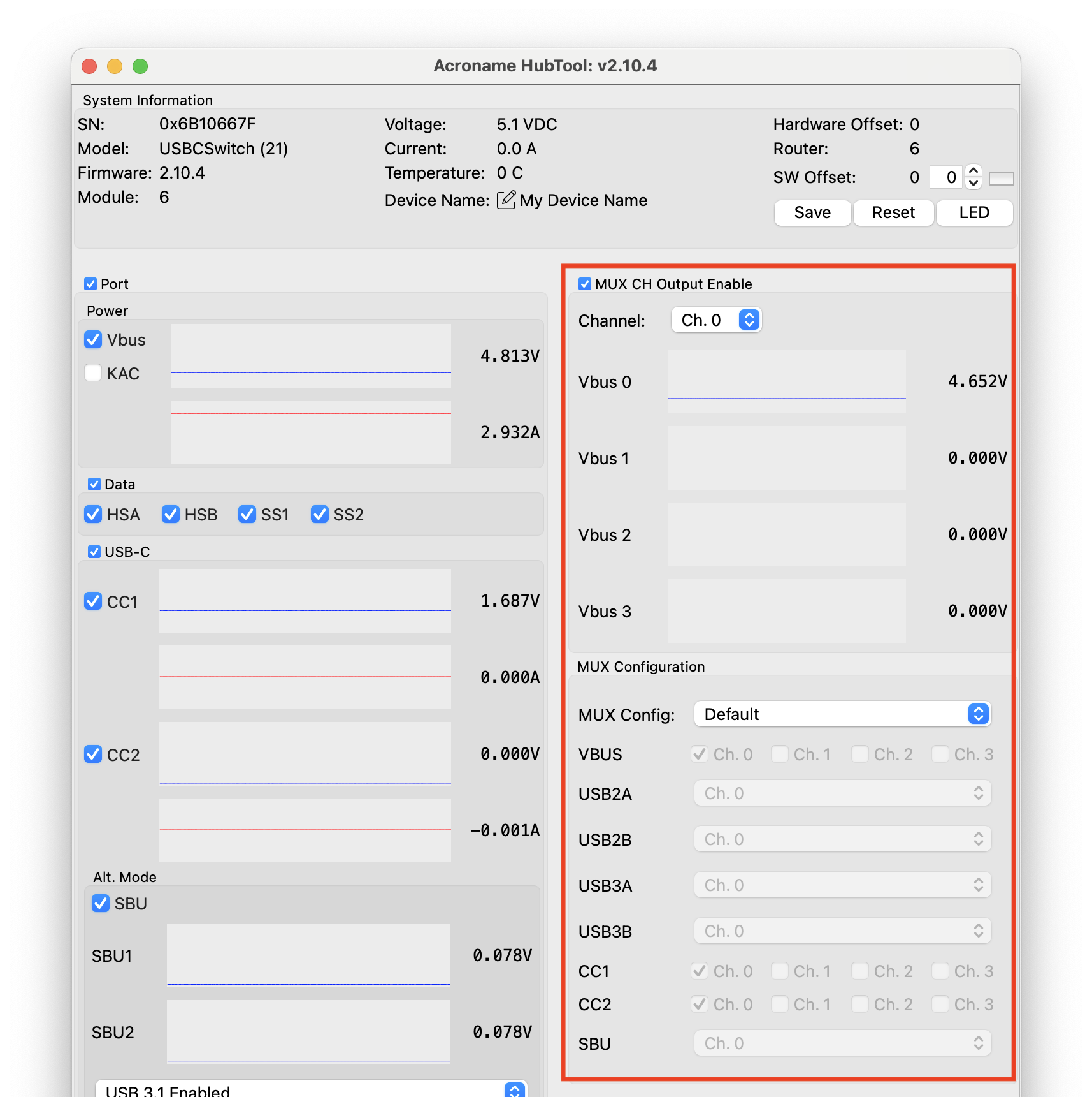
HubTool presents a unified dashboard to control and view the state of USB-C-Switch.
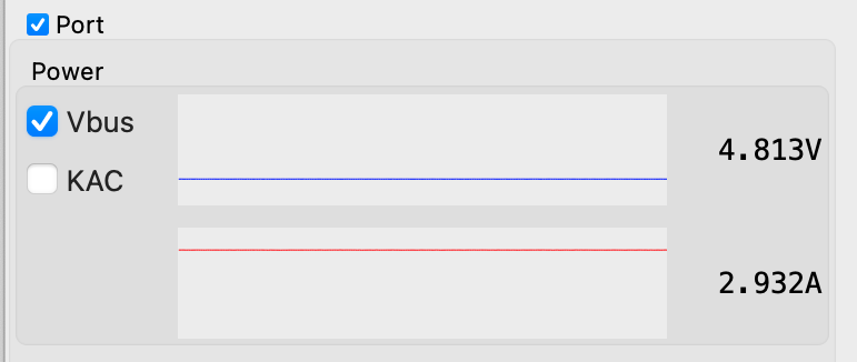
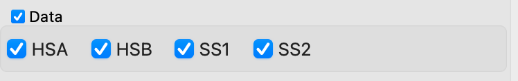
Port toggle – enables and disables all lines connecting the Common port to the selected mux channel
VBus toggle – enables and disables VBus lines
KAC toggle – enables Keep-alive charging (KAC)
Keep-alive charging helps keep battery-powered devices on the non-selected mux ports charged. When enabled, the KAC circuit connects power from the control port VBus to all non-selected mux channel VBus lines. See the API reference <cs-kac> for more detail
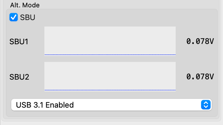
SBU toggle – enables and disables SBU lines. Used for Alternate Mode discovery, negotiation, and configuration data exchange
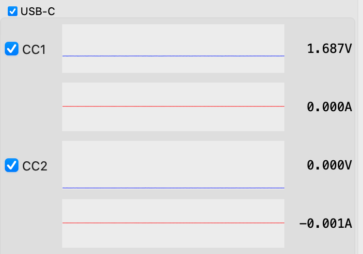
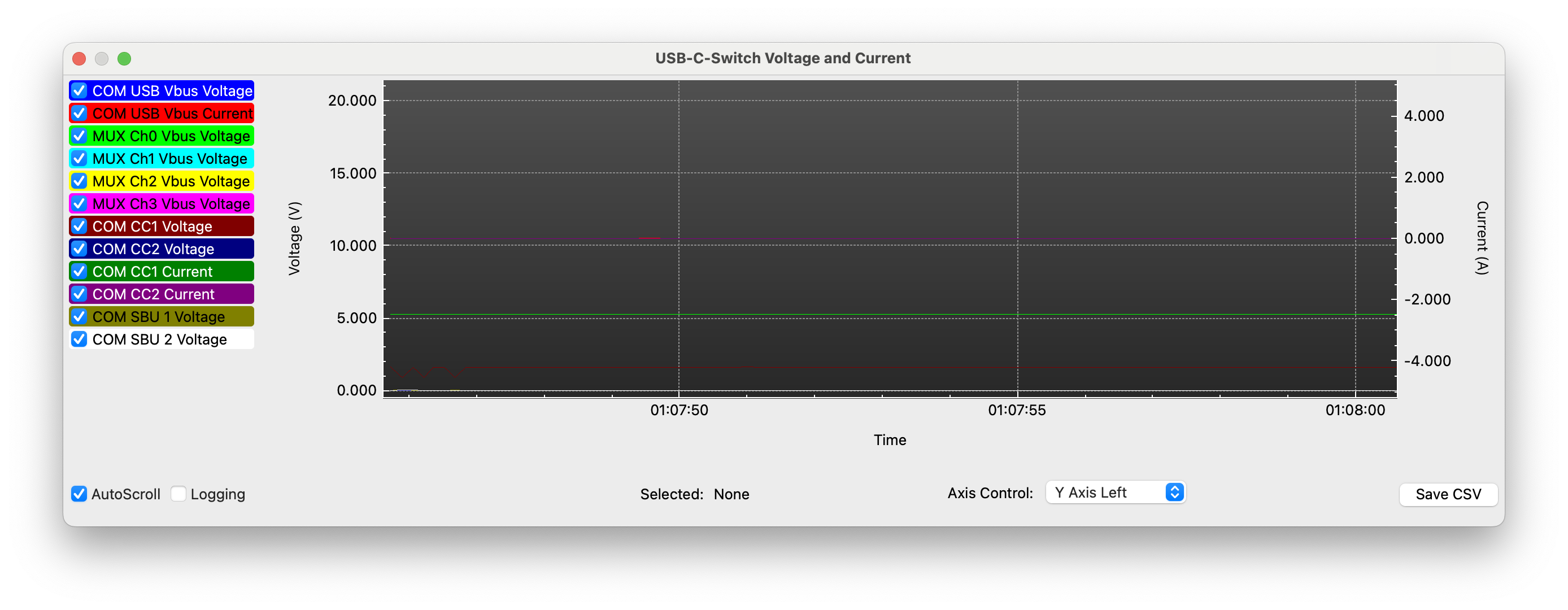
SBU1 and SBU2 voltage and current plots (redriver model only) – shows voltage and current for SBU1 and SBU2. Click to pop up the Voltage and Current plot window
DisplayPort alt mode configuration menu (redriver model only)
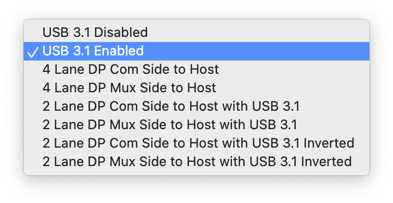
Alt Mode Configuration
USB 3.1 Disabled – no SS lines connected
USB 3.1 Enabled – SS lines connected
4-Lane DisplayPort – no USB 3.1 – Host on Common Port
4-Lane DisplayPort – no USB 3.1 – Host on Mux Port
2-Lane DisplayPort + USB 3.1 –- Host on Common Port
2-Lane DisplayPort + USB 3.1 –- Host on Mux Port
2-Lane DisplayPort + USB 3.1 Inverted – Host on Common Port
2-Lane DisplayPort + USB 3.1 Inverted – Host on Mux Port
DisplayPort Alt modes use the SS lines for DisplayPort data, but change their direction. Since each redriver line can operate in only one direction at a time, the redriver direction needs to be set to match the mode being used by the host and display. See the :ref: API reference <cs-alt-mode-configuration> for more detail.
Cable flip toggle – switches USB data, VConn, and SBU lines from side A to side B as if the cable had been flipped. When using standard USB-C cables with USB-C-Switch, one cable orientation will work, the other will need to be flipped physically, or by using the toggle.
CC, SS, SBU, USB2 flip toggles – individually flip each connection type
To enable automated cable flips for testing, use one Universal Orientation Cable for either the host or mux connection, and one standard cable for the other connection.
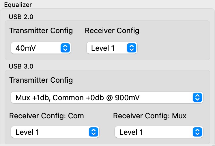
The equalizer section provides controls to set transmitter and receiver gains for USB 2 and USB 3 data lines in both directions.
USB 2.0
Transmitter config – selects the amount of DC boost applied to USB 2.0 (HS) signals. USB Low Speed and Full Speed signals are unaffected. When boost is set to O mV, the HS redriver is disabled independent of receiver configuration
USB 2.0 transmitter DC boost
40 mV – default
60 mV
80 mV
0 mV (redriver disabled)
Receiver config – controls the sensitivity of the redriver to incoming HS signals by boosting higher frequencies to make sharper edges. When receiver config is set to level 0, the redriver is disabled independent of transmitter configuration
USB 2.0 Receiver Equalization
Level 1 – moderate boost – default
Level 2 – higher boost
Level 0 – redriver disabled
USB 3.0
Transmitter config – selects preset combinations of transmitter gains for each direction of the full-duplex USB 3 (SS) data lines, and peak-to-peak voltage for both directions
Mux Side
Common Side
Range
1 db
0 db
900 mVpp
default
0 db
1 db
900 mVpp
1 db
1 db
900 mVpp
0 db
0 db
900 mVpp
0 db
0 db
1100 mVpp
1 db
0 db
1100 mVpp
0 db
1 db
1100 mVpp
2 db
2 db
1100 mVpp
0 db
0 db
1300 mVpp
Receiver config: com – sets the sensitivity of the redriver to incoming SS signals on the com side by boosting higher frequencies to make sharper edges. Level 1 (lowest boost, default) to Level 16 (highest)
Receiver config: mux – sets the sensitivity of the redriver to incoming SS signals on the mux side by boosting higher frequencies to make sharper edges. Level 1 (lowest boost, default) to Level 16 (highest boost)
Default – switches all enabled USB-C lines to the single mux port designated by the channel selector
Channel priority – auto-selects the lowest-numbered mux port that has VBus present. Allows simple automatic host selection (requires USB A-to-C cables)
Split – allows each signal type to be independently connected to a mux port. VBus and CC lines can be assigned to any combination of ports, while USB2, USB3, and SBU can be assigned to a single mux port. See the API reference for more detail