What's a USB device tree, and why is it important for conference room A/V?
Understanding the USB Device Tree
Acroname's ControlRoom web-based software works with our intelligent USB hubs to visualize the USB device tree of the host.
USB has the concept of tiers: the host and root hub are on the first tier. A device connected to the root hub is on the second tier. If a hub is added in between the device and the root hub, the device moves down to the third tier. Up to 5 non-root hubs can be added in series for a maximum of 7 USB tiers (5 Hubs + root hub + device)
The USB Tree provides a simple visualization of the USB tiers along with each device and how it is connected back to the host controller.
Let's look at a conference room example:
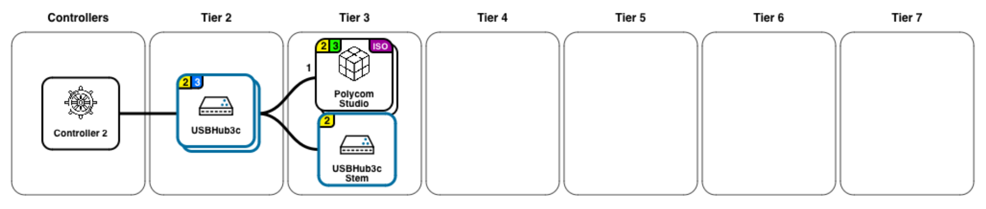
Acroname and ControlRoom: Revolutionizing Conference Room A/V
Here, a Poly Studio video bar is connected to an Acroname hub.
- Controller - USB controller in the host PC
- USBHub3c - Acroname USB-C hub, allowing for automatic BYOD host switching
- USBHub3c Stem - Microcontroller that communicates with and controls the hub. Internally connected to the hub by USB 2
- Polycom Studio - Poly Studio USB Video bar
Zooming in on the Poly Studio, we see more device information:

- Connection speed - "1", "2", or "3" indicating USB 1, 2, 3.
- USB 2 and 3 are active, the green "3" indicates a 5 Gbps connection
- Hub port number - port 0 - 5 on USBHub3c
- Device feature - "iso" indicates that the device is capable of streaming isochronous data
The Significance of USB Hubs in A/V Configuration
Below the USB tree is the port view:
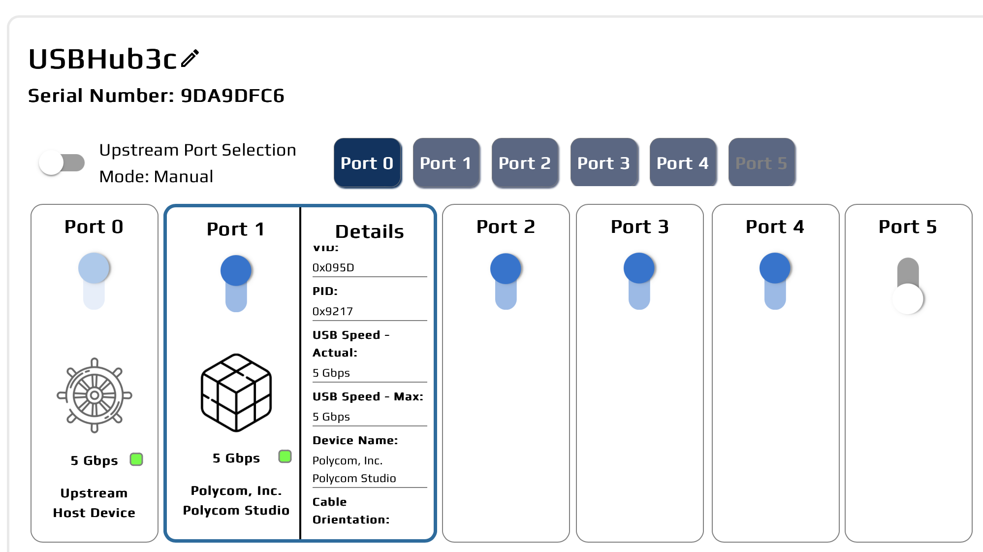
The port view provides detailed control and information per port. Toggles allow each port to be cycled to reset stuck devices.
In the details pane, we can see even more realtime information about the video bar:
- Current
- Voltage
- Power
- Serial number
- Vendor and Product ID
- Actual and maximum USB speeds
- Device manufacturer and device name
- Cable information (if advertised):
- Cable current max
- Cable voltage max
- Cable speed max
- Cable orientation
- Cable type
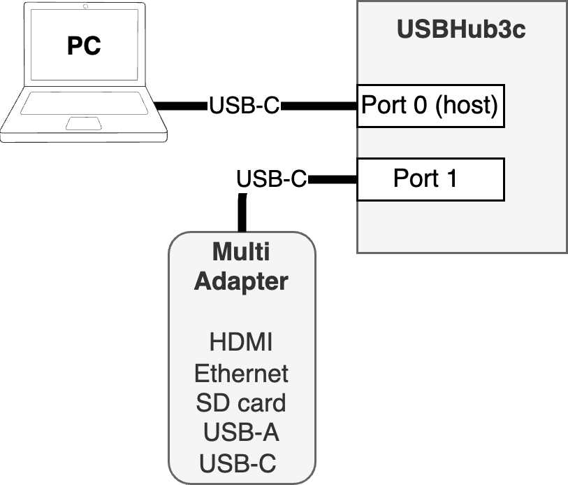
How is the USB tree different from a cabling diagram?
Let’s look at what might seem like a simple setup. The host is connected to an Acroname Hub on port 0, and a single multi-adapter (HDMI, USB-A, SD card, ethernet) on port 1:
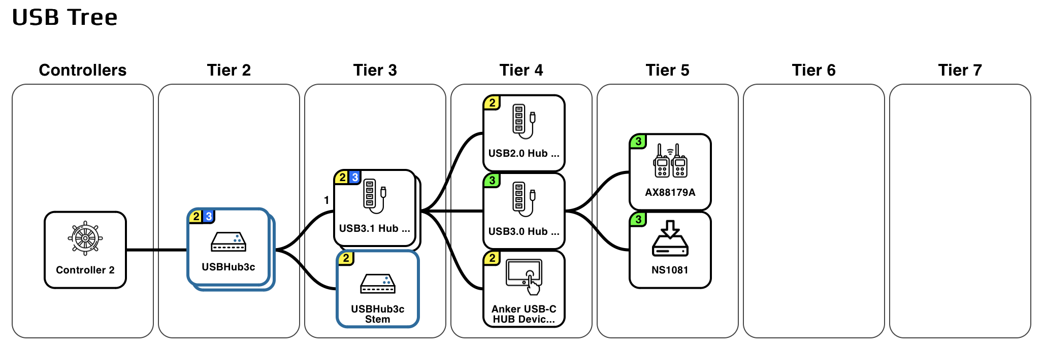
Let's draw borders around which elements live in which enclosures:
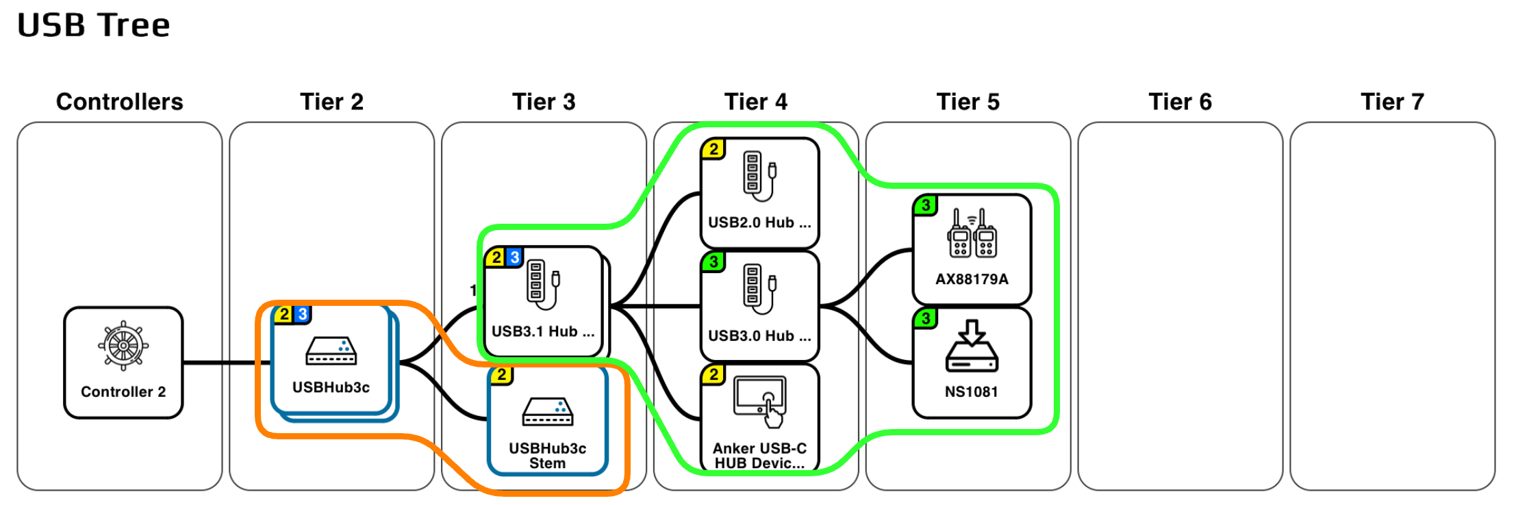
USBHub3c is in the orange border. The hub itself is on tier 2, shown as a stack and with a yellow "2" and blue "3' indicating that both USB 2 and USB 3 hubs are present, with USB3 connected at up to 10 Gbps.
- USBHub3c Stem is the "brain" that can connects to the host PC and provides control over the functions of the hub and reports information like data rate and voltage and current for each port. It is connected internally to the USBHub3c as a USB 2 device, indicated by the yellow "2"
The Multi Adapter is in the green border.
Tier 3
- USB3.1 Hub on tier 3 is the adapter's top level hub, shown stacked and with a "2" and blue "3" indicating that USB 2 and USB 3 (10 Gbps) are supported
Tier 4
- USB3.0 Hub connected via USB 3 ("3" in green indicates 5 Gbps)
- USB2.0 Hub and Anker USB-C Hub device connect via USB 2
Tier 5
- AX88179A gigabit ethernet adapter connected vis USB 3 (5 Gbps)
- NS1081 SD card adapter connected via USB 3 (5 Gbps)
So within the multi adapter, we have two USB 2 hubs, and two USB 3 hubs.
Note: USB 2 and USB 3 signals are on separate wires, and each protocol gets its own hub. USB 2 and USB 3 are completely separate busses that happen to run in the same cable jacket and the hubs share enclosures.
The Benefits of Understanding Your Conference Room A/V USB Tree
Performance and future proofing
- Each tier adds some overhead, high bandwidth devices should generally live on the lower-numbered tiers of the tree, closest to the host. This is especially important for isochronous devices like cameras
- USB extension cables usually contain a hub, adding a hidden USB tier
- A USB 2 cable forces downstream devices to lower 480 Mb/s speed.
- USB 3.1 is more than 20x the speed of USB 2, so the effect can be significant
- Having more devices fall back to USB 2 also can create bottlenecks on the USB 2 network
- Catch if someone accidentally grabbed a USB 2 cable from the unlabeled cable bin!
- Allow for future expansion by having more ports available at a lower-numbered tier
Documentation, repeatability and validation
- Once a "gold master" conference room has been assembled, ContolRoom lets you save the USB tree as a PDF to use as a recipe for multiple installations. This allows installers to "copy exactly"
- Differences from a loaded recipe are automatically highlighted, making it easy to spot problems during installation
- Ongoing maintenance: spot changes in each conference room USB tree -- did someone "borrow" a cable?
Comparing with a saved USB tree
The USB tree information is saved as a special PDF file that shows the tree diagram and embeds a representation of the USB tree that can be read by ControlRoom. You can upload a saved USB Tree PDF file to dynamically compare it to the current tree.
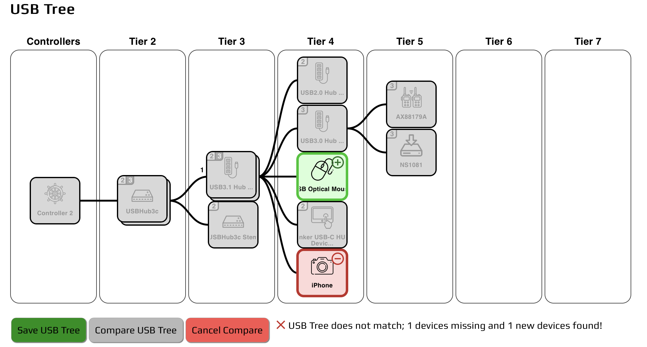
USB devices that match the loaded USB Tree recipe will show a gray background. Missing devices will be shown in red and new devices in green. If a device has been moved to a different port, it will appear twice, once in green as new, and once in red as missing. Changes in the USB tree appear immediately, allowing for interactive debugging.
USB doesn't have to be a mystery -- ControlRoom lets you optimize your USB tree, see what your devices are doing, and catch problems early!
Add New Comment