
A new paradigm of testing created a low-maintenance, high-throughput, scalable automated test-system
ABSTRACT
Adoption and integration of USB-C chargers and hubs in automotive applications is driving a need for an updated approach to production tests due to USB-C’s connector density, high bandwidth, and high power. We introduce a new paradigm in test-system development, micro-FCT (micro Functional Test), and demonstrate developing and deploying of an end-of-line (EOL) functional test-system which meets the strict automotive test requirements for a USB-C hub. Specification to deployment of the test-system was completed in less than 10-weeks, and test cycle time was 1/10th of the customer’s requirements.
I. INTRODUCTION
A major European test automation service provider, Kentigen s.r.o., was contracted by a Tier-1 automotive OEM to develop a next generation, end-of-line (EOL), automated production test-system for an automotive USB-C hub module. This next-generation solution was commissioned to add USB-C specific features and to address key shortcomings of the previous-generation production test-system: long test cycle times; frequent system maintenance; unplanned production downtime due to equipment failures. Kentigen used a novel, micro-FCT approach to test-system architecture design to fulfill the customer requirements while maintaining system scalability against a strict 10-week deployment deadline.
Kentigen’s solution was based on Acroname’s Manufacturing Test Module (MTM) instrumentation which minimized the test-system wiring complexity and maximized instrumentation density. MTM’s micro-FCT approach enabled all needed test equipment to be directly connected to the Unit Under Test (UUT) while maintaining USB data signal integrity. MTM also allowed key measurement tasks to be parallelized by utilizing instrumentation with high-density, independent measurement channels. These parallel measurements reduced overall test time and eliminated failure prone mechanical relay-matrices normally used to serialize measurements to a single channel measurement instrument. The micro-FCT based test-system resulted in a reliable and high-throughput USB-C hub test solution which quickly scaled across multiple production cells. The micro-FCT approach was key to both gaining customer confidence and accelerating time to market. We review and describe some key micro-FCT design methods adaptable to any USB-C hub functional testing.

FIGURE 1. A typical dash-mounted automotive USB hub module (courtesy of https://www.ramtruck.ca)
Problem Statement
Functional testing of USB-C requires in-depth knowledge of the USB-C connector definition, USB 3.1 specification, and USB power-delivery (USB-PD) specification. In particular, it is important to consider the various bandwidth requirements for data connections, and high-power potential of the USB Vbus. Specific test definitions will vary by which parts of the specifications a particular device implements. In general, a functional test for a USB-C hub should include:
- Open/short continuity measurements between pins to ensure UUT functionality and user-safety
- DC-resistance measurements on Vbus and ground pins
- Vbus current and overcurrent up to 5A
- CC and Vconn flipping based on cable orientation
- Vconn current capability
- Bandwidth compliance of all data signal pairs
- Host-to-device enumeration at supported data rates
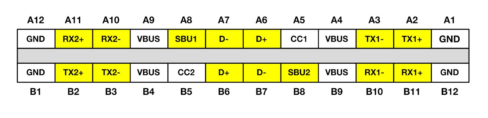
FIGURE 2. The USB-C connector pinout definition with high speed data lines highlighted.
Challenges
Implementing these types of tests independently is not particularly challenging. Implementing all these tests in one test-system is only challenging when trying to optimize for cost and size. USB-C presents some additional challenges:
- The high pin-count and high density USB-C connector has a high probability of assembly complications and resistive shorts which can cause irreparable damage to a UUT or connected end-customer device.
- Multiple Vbus and ground (GND) pins which are shorted on the UUT require independent connectivity verification.
- Strict safety-ground requirement for isolation between the test-control computers and the UUT while maintaining USB data connectivity which relies on continuous (bonded) grounds.
- USB HighSpeed and SuperSpeed signaling use relatively low signaling levels, and higher test voltages or currents can damage the UUT.
- A customer requirement for the test-system to provide passive USB pass-through requires unobstructed USB data paths.
- Standard USB-C to USB-C cables do not provide clean CC1/CC2 signal paths and define the connector orientation.
- Parasitic coupling between the data line differential pairs may present as resistive shorts.
These challenges are surmountable with a standard test-system design approach, but the resulting test-system may require costly, high bandwidth switches. Also, the high pin-count requires a large dimension switch matrix in order to make all the needed open, short and resistance measurements.
In addition to challenges affecting all USB-C testing, the customer for this test-system presented the additional challenges of needing the test-system to test 10 UUTs in parallel in a very small test cell footprint and accommodate several UUT variants with:
- Each variant having different USB port counts split between USB Type-A and USB-C connectors.
- Some UUT variants only support data communications on particular ports or only at certain data rates.
- UUTs with different overcurrent limits.
Kentigen’s creative solution of interchangeable mechanical interface heads mounted to a robotic turret solved many of the challenges created by the UUT variations. The remaining challenges were addressed by the agility of the micro-FCT design approach and many unique features of the MTM instrumentation. Testing 10 UUTs in parallel in the small cell footprint was able to be accomplished with MTM’s high measurement density. Perhaps most challenging, the customer required a very short deployment schedule: development and deployment at scale had to happen within 10 weeks.
II. PAST METHODOLOGY
Serialized Measurements
Kentigen and their customer had previously deployed test-systems with similar requirements which utilized large dimension relay-matrices coupled to a high-precision digital multimeter (DMM). Although utilizing relay-matrices is quite common in production environments, the main reason it is used is due to the expense of the measurement instrument, in this case the DMM. Using one measurement instrument and expanding its connections using a relay bank can reduce the total test-system cost compared to using multiple measurement instruments. Unfortunately, such a design forces serialized measurement tasks since each signal must be selectively coupled to the measurement instrument with the appropriate chain of relays. In a test-system executing many thousands of measurements, the serialization of these measurements culminates in unreasonably long test cycle times.
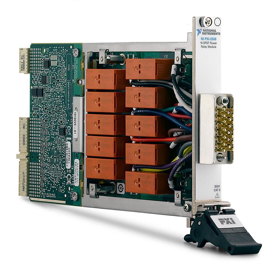
FIGURE 3. A typical PXI-based mechanical relay switching module.
In Kentigen’s previous test-systems, the large number of mechanical relays were costly and required significant manual wiring, even after fabricating a custom printed-circuit board (PCB). These relays provided connectivity and isolation for all continuity, voltage, and current tests. As such, the relays went through thousands of contacting cycles for each test cycle. Even with regular maintenance, the test-system experienced significant unplanned downtime due to failed mechanical relays. Replacing these components on a frequent basis created unexpected and costly production line downtime.
The previous test-systems’ reliance on mechanical relays also created a requirement for long delays between measurements. As is common with mechanical relays, their contacting exhibits “bounce” which creates voltage transients that can cause DMMs to erratically switch ranges. To mitigate false-failures, the test-system needed to add “settling time” delays between relay switches and measurement. Measurements from the DMM also need to be repeated and filtered. All of these issues added significantly to the test cycle time.
USB Functional Test
The previous test-systems relied on a USB flash drive to test the USB data connection. Typically, this involves mounting the flash drive as a mass-storage volume, writing a known file to the volume, reading the file back from the volume and verifying the contents. Again, this is a common method that is frequently implemented in production test-systems. Real-world shortcomings of this approach include: limited lifetime and intermittent failures of flash drives, variation in the read/write performance over time and between drives, accounting for additional test cycle delays due to volume mount/unmount times, and corrupted volumes due to frequent or improper volume unmount procedures.
III. MICRO-FCT BASED SYSTEM
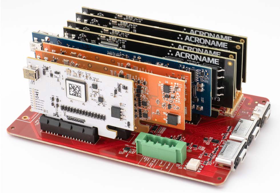
FIGURE 4. The test-equipment assembly for Kentigen’s micro-FCT test-system showing the Acroname MTM modules mounted on a PCBA for interface to the USB-C cables from the UUT.
Continuity Checks A micro-FCT test-system design methodology starts with using equipment well matched to the task. In following this paradigm, it can be advantageous to think about how standard benchtop test equipment performs particular measurements. One major measurement task required in this test-system is 576 open/short continuity measurements; that is checking each of the 24 pins on a USB-C connector to all other pins (24 x 24). A DMM can be used to perform these measurements, but a DMM includes a lot of other functionality that is not used in this test-system. Breaking down how a DMM performs this test, it may be possible to optimize the test-system.
A DMM continuity test applies a small current source between its terminals and simultaneously measures the voltage across the terminals. From the values of current and voltage, the resistance is determined; resistance below a defined threshold triggers a continuity indicator. The actual implementation of this circuit varies, but the simplest approach is a resistive connection to a precision voltage source. In our specific and controlled application, this simple circuit is more than adequate.
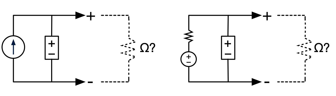
FIGURE 5. Equivalent circuits for resistance measurements.
Using a DMM to check continuity is straightforward, yet checking 576 unknown resistances is costly simply due to making the necessary connections. Traditional test-system design methods would use relay-matrices to move the DMM terminals between the various measurement points. In the micro-FCT approach, the test-system is not limited to the standard DMM interface and can split the problem in the middle. The location of the current-source can be split by using a series resistance on the positive and negative terminals of the voltage source.
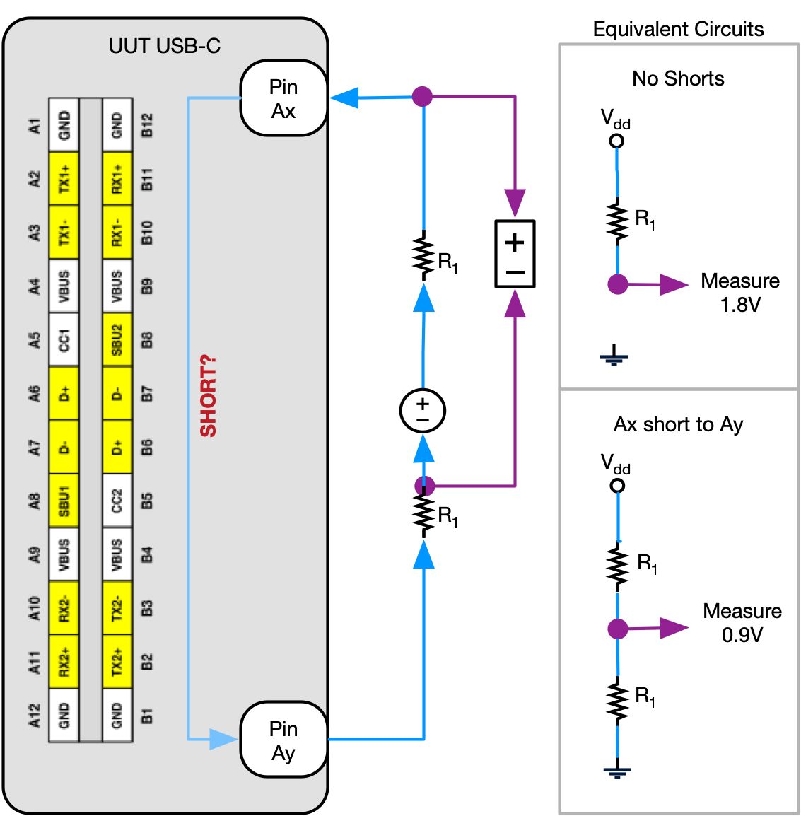
FIGURE 6. Continuity measurement with split resistance.
It might not be immediately obvious why this split-resistance continuity measurement is advantageous. The advantage is that with simple tri-state digital outputs, the test-system can rapidly change where the continuity test current is applied to the UUT. A further advantage is that by splitting the resistance between the two measurement terminals, a single measurement can rapidly check for shorts and resistive-shorts between not just one pair of pins, but also between one pin and all other pins. That is, pin Ay in Figure 6 can be the set of all pins other than Ax . Figure 7 shows the test-system’s implementation with tri-state drivers testing for continuity between Ax and two other pins Ay and Az .
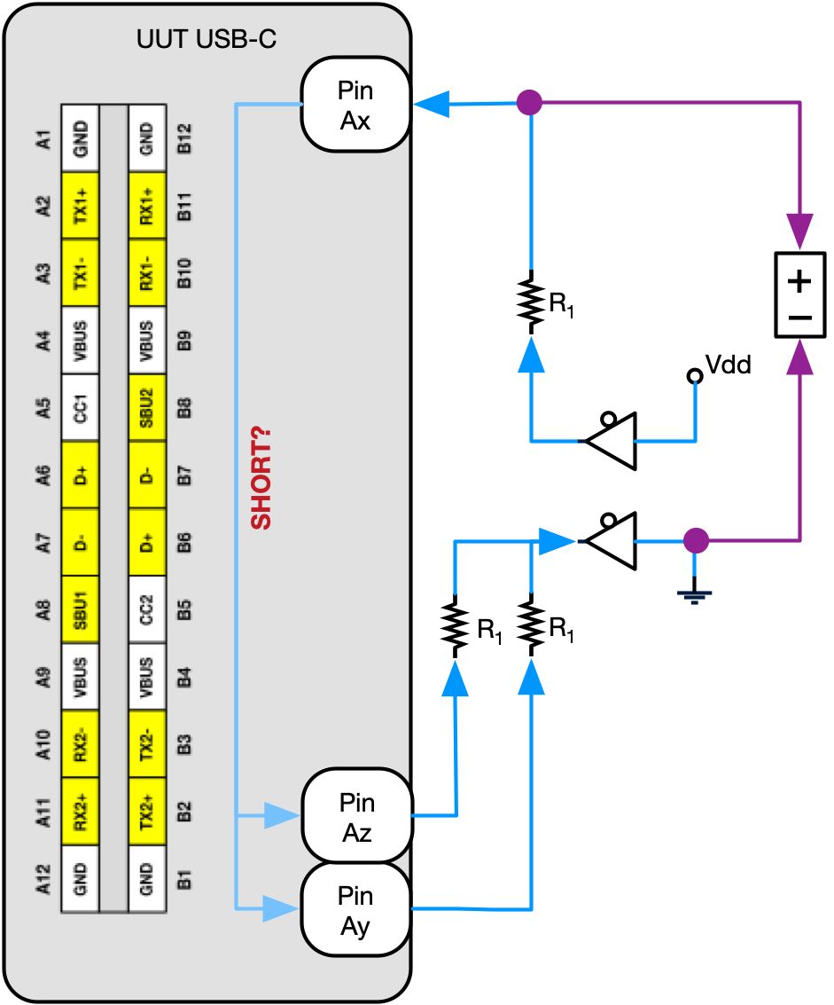
FIGURE 7. One-to-many continuity measurement with split resistance and tri-state drivers
This concept highlights another micro-FCT paradigm: manufacturing test-systems should target an output of “ship” or “no-ship”. Further quantification of results may be required for setting test limits and process control, but additional cost should not be incurred in the test-system to aid in failure-analysis.
In this particular case, the test-system is capable of executing an in-depth test to identify continuity between all 576 pin-pairs. These results can be useful in directing a failure analysis engineering investigation by highlighting exactly which pins show improper continuity. Alternatively, the test-system can simply check if each pin has the expected number of continuity connections to any other set of pins. On the standard USB-C connector, half of the pins have no intentional shorts to other pins; 4 pins may have a short to one other pin; and 8 pins have intentional shorts to 3 other pins. The subsetting of pin continuity checks in this fashion dramatically lowers the number of measurements required and thus reduces the test cycle time.
A traditionally designed test-system capable of executing the high number of continuity measurements needed to verify proper manufacturing of a device with a USB-C connector would require a large dimension one-to-any relay matrix coupled to a DMM. Utilizing micro-FCT design paradigms, the test-system is simplified to resistors, tri-state digital outputs and voltage measurements.
The close observer will recognize that this system will need a voltage measurement connection on each pin or at least pin-group. A one-to-common relay bank could be used to selectively connect each pin to a DMM. In this case, Acroname’s MTM modules offer a better solution. The MTM-DAQ-2 offers 16 input channels per module for less cost than a typical software-controlled DMM. Networking the MTM-DAQ-2 modules extends the measurement capabilities in minimal physical space allowing a 1:1 measurement node to instrumentation input. Using a large number of parallel input channels for the voltage measurement dramatically reduces test cycle time by eliminating settling time associated with mechanical relays and DMMs.
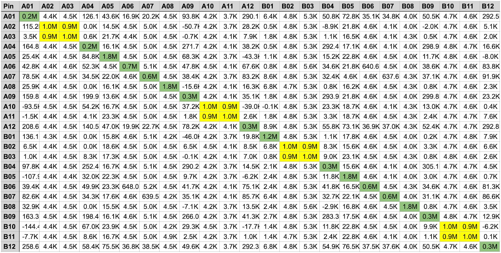
FIGURE 8. Example of continuity verification results (arbitrary units).
The resulting continuity measurement data can quickly show expected patterns of proper USB-C connections. Figure 8 highlights (in yellow) expected shorts between USB SuperSpeed pairs, the 4 pins for Vbus, and the 4 pins for GND. The SuperSpeed resistive-shorts are due to parasitic coupling between the differential pairs as part of 2:1 multiplexers in the test-system and UUT. The Vbus and GND pin groups are shorted together intentionally by design to handle higher charging currents. The diagonal (green) highlights the self connection of each pin.
USB Functional Verification
While critical parameters impacting USB data signal integrity are “correct by design” and are not significantly impacted due to variation in the manufacturing process, many manufacturers require a true functional test of USB data paths. A brief understanding of how the USB physical layer operates can help design an optimal functional test. For USB 2.0, after completing a low-speed reset and full-speed detection, the USB 2.0 enumeration process includes a signaling integrity test with a worst-case, high-speed signal. As such, a device that enumerates at high-speed will also transfer arbitrary data at high-speed with very high probability. Simply enumerating a device at high-speed is a sufficient functional test.
Functional testing of USB can be further optimized through better understanding of the host side USB enumeration process. USB defines several native device types. These device types are supported with built-in drivers on all modern host operating systems, and these drivers are the fastest and most robust device drivers available. One of the simplest native USB devices that supports higher data rates is a hub device.
With this understanding of USB drivers and the enumeration process, a test-system needing functional USB verification of a USB 2.0 high-speed interface can most optimally be tested by simply enumerating a high-speed capable hub. This test method eliminates issues with file system drivers and slow enumeration of higher level device drivers.
Output Loading
USB standards before USB-C offered a simple 5.0V Vbus supply with varying current supplying capacity. It is relatively simple to test the Vbus on devices supporting these old standards by applying loading conditions up to and above the device’s current capability with resistive or active loads. USB-C interfaces introduce a functional testing challenge by requiring power-sourcing devices to disable Vbus power until an indication is observed on one of the Configuration Channel (CC1, CC2) pins. Cable and device connection presence as well as the physical cable orientation is defined by a bias on the CC pins. This new feature requires a USB-C test-system to emulate these connection and cable-orientation indications independently on both CC1 and CC2. Note that the target UUT in this application only supported the USB-C standard and not the USB-PD standard.
The target UUT USB-C hub for this test-system implemented the 15W (5V at 3A) USB-C profile which is accomplished with static voltages applied to the CC pins. Functional verification of these source-only, single-profile devices can be performed by checking the presence of the appropriate current source or pull-up (Rp ) on each CC line. Then, the test-system can signal to the UUT to energize the Vbus power by applying a specific pull-down resistor (Rd ) to each CC pin independently. After Vbus is energized, load testing can be performed by applying resistive or active loads between Vbus and GND.
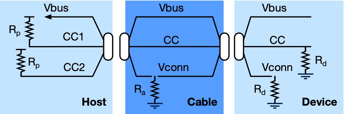
FIGURE 9. USB-C presence and orientation determination equivalent circuit.
Similar to the micro-FCT design approach used in USB data verification, understanding the standards supported by the UUT and the associated physical interfaces vastly simplifies this test-system. This micro-FCT approach can be applied to functionally testing the UUT’s power sourcing capability.
Kentigen’s test-system verified the unloaded presence of the UUT’s profile by verifying the Rp on each CC line. The test-system then used tri-state drivers with series connected Rd resistors on CC1 and CC2 to signal to the UUT the presence of a downstream device. The test-system also verified the correct static voltage after the connection of Rd on each CC line in order to verify the value of the UUT’s Rp . Appropriate CC signal and Vbus power path routing was switched through the micro-FCT interface to an external connector interface where Vbus was coupled to an active load which performed voltage, current, and power analysis.
USB-C CC and Vconn Verification
It is important to note that standard USB-C cables define the connection orientation and thus define which CC pins should be used for power negotiations. Standard cables implement this using a built-in pull-down resistor (Ra ) or electronic-marker (eMark) circuitry embedded in the cable. Cable orientation introduces another challenge when testing USB-C devices that would either prevent the testing of both sides of the USB-C connector interface or require an operator to physically unplug, rotate, and reconnect the cable at the UUT. To overcome this challenge Acroname’s Universal Orientation Cable (UOC) removes this orientation definition in the cable. The UOC cable is an integral part of any fully automated USB-C test-system.
One final complication of the USB-C standard is the potential eMark hidden in the cable. This circuitry can draw up to 1W (5V at 200mA) of power from the CC lines. This is an often overlooked, important functional test for any USB-C device. Kentigen’s test-system similarly routed the unloaded CC lines to an active load for power analysis.
IV. APPLICATION SOFTWARE
Kentigen’s customer required the system to be based on National Instrument’s TestStand software to facilitate integration with the local test cell’s test-result collection and analysis system. The test software also connected to the customer’s shop floor control system. The software coordinated control of a robotic arm and turret for loading and testing 10 UUTs with the execution of functional tests. Some of the motion-control was adopted from previous test-systems, and the adoption of the previous software for this new test-system was done in parallel with the development of the functional test-system.
The functional measurement software was first prototyped in Python. The consistency of the application programming interfaces (APIs) offered by Acroname’s MTM equipment made the transition from the prototype Python to production TestStand software nearly effortless. Much of the code was able to be translated with only minor syntax changes.
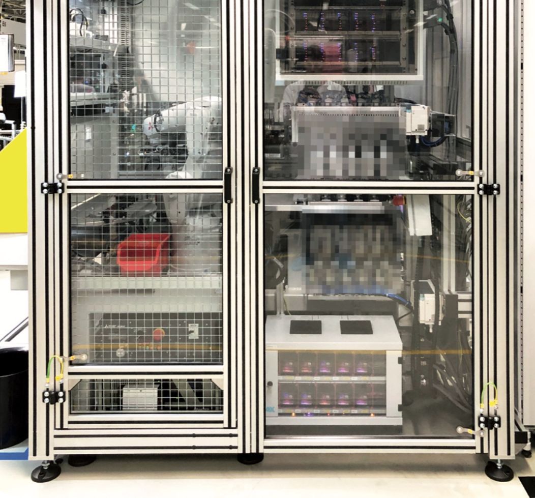
FIGURE 10. Full Kentigen USB-C hub test-system showing robotic arm loader, turret and measurement equipment.
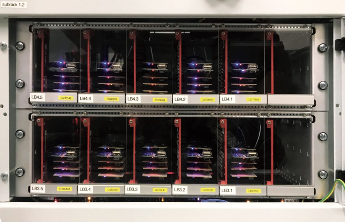
FIGURE 11. Detail of measurement equipment showing one group per UUT position to enable fully parallel test execution.
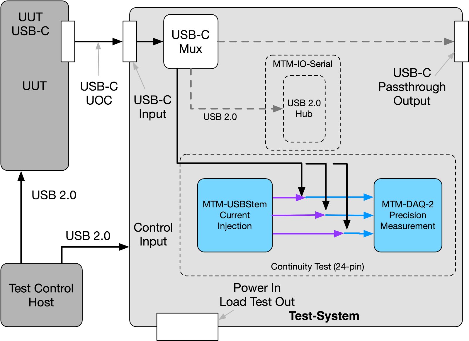
FIGURE 12. Functional block diagram of a test-system for a USB-C hub designed using micro-FCT paradigms and implemented with Acroname’s MTM modules.
V. RESULTS
Cycle Time
The test-system executed the full continuity test, totaling thousands of test steps and measurements in 1.7 seconds. Not only was the customer impressed, the first time they saw the continuity test execution they jokingly said, “can we slow this down? It’s too fast; our customer won’t believe it’s doing all those tests.” Instead of slowing it down, Kentigen demonstrated how the system could actually execute the test faster by accounting for the pin groups known to be shorted on the UUT.
With all of the power loading tests and UUT firmware flashing included, the test-system cycle time was 17s for all 10 UUTs. Most of the test cycle time was waiting for the UUTs to reach the desired temperature during the high-power load tests.
The micro-FCT design approaches and MTM instrumentation resulted in an 87% reduction of test cycle time from previous test-systems.
Reducing Cost and Saving Space
An important factor when designing a test-system is the consideration of its required floor space. Contract manufacturers are constrained in their throughput and revenue potential by how many test cells or stations they can fit into their manufacturing space. A test-system designer should optimize for production-throughput per floor space area. Acroname’s MTM modules are specifically designed to provide the highest possible test-function density without the requiring expensive and large 480mm (19 inch) racks or interface chassis. When standard racks are needed for other equipment, the MTM modules slot nicely into standard 2U or 3U PCBA mounts.
As compared to traditional PXI instrumentation, the test-system’s MTM instrumentation cost approximately 70% less and occupied just 25% of the volume. For the same cost as a PXI chassis, controller, and one 24-channel data acquisition module, this test-system’s instrumentation offered 320 channels of analog measurement, 470 tri-state digital inputs and output, 160 solid state power relays, 40 switchable USB ports, 40 serial interfaces and 30 programmable voltage sources.
Endurance
The micro-FCT design approaches eliminated 75% of the test-system wiring and resulted in a nearly maintenance-free system. The test-system has run 24/7 with no unplanned downtime after more than 15 months in service.
Finally, based on the reusable nature of the instrumentation modules themselves, when this project endsor changes, the instrumentation can be repurposed into the next system.
Development Time
The test-system development took 10 weeks from specification to deployment at the customer’s site. The micro-FCT design approach enabled rapid development of the test methods. Acroame’s MTM modules’ flexible and user-definable hardware interfaces allowed for various subsystems to be developed in parallel. Simple and consistent software APIs enabled seamless transitions from prototyping to validation to production.
VI. CONCLUSION
“Our customer is pleased with the improved cycle time performance and virtual elimination of maintenance which we were able to achieve by using MTM instrumentation”, said Mr. Šantavý, Managing Director, Kentigen s.r.o. Acroname’s MTM instrumentation enabled Kentigen’s engineers to realize and deliver a new paradigm of functional test-system based on the micro-FCT approach. The test-system is more reliable, lower cost to build, simple to replicate, lower cost to design, and faster to deploy. MTM and micro-FCT can enable your test team or test service provider to recognize similar successes.
For more information about micro-FCT and Acroname’s MTM instrumentation, contact sales@acroname.com.
For detailed information about this automotive USB-C hub test-system or custom test-system development, contact info@kentigen.com.
Add New Comment