Connectivity and Control of the Acroname USB-C-Switch
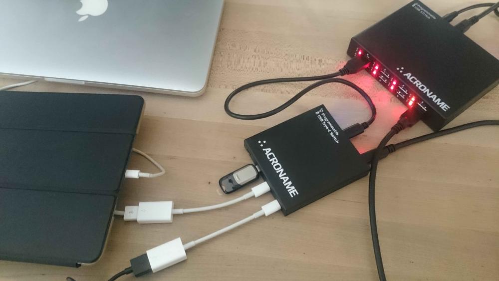
Acroname’s BrainStem-enabled programmable USB-C-Switch can be very useful to help automate and monitor USB connections in test environments. USB-C-Switch handles USB connections differently than a USB hub and also introduces the MUX entity to the BrainStem function libraries.
In this blog post, we will illustrate the connectivity and control aspects and show a control example in Python.
Control Port:
Power and control the USB-C-Switch
The Control Port allows a host machine to access the BrainStem controller inside the USB-C-Switch. The BrainStem controller responds to the BrainStem API requests from a connected host machine and manages internal functions of the switch.
Power for the switch internal electronics and for the Keep Alive Charge (KAC) function is provided from the Control Port connection. Detailed description of KAC operation is beyond the scope of this post and will not be covered here.
It is possible to connect to and develop software for the USB-C-Switch using only the Control Port connection.
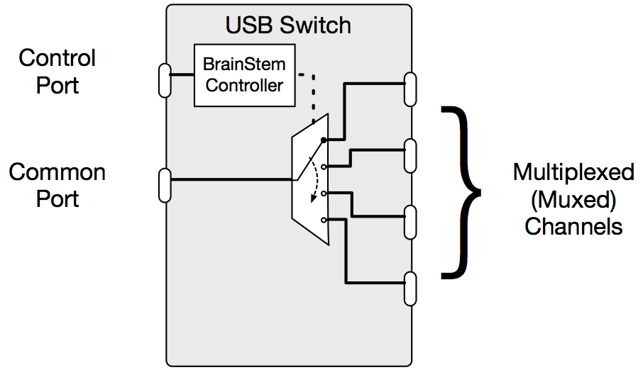
Figure 1: Control Port provides power and BrainStem API access
Data Path
Create a selective connection
A USB switch is a 1:N or N:1 device which creates a selective connection between the Common Port and one selected channel. Like a cable, the switch is passive and creates a dedicated, bi-directional connection from the Common port to the selected device.
In very simple terms, the USB-C-Switch behaves like a USB-C cable, where one end is tethered to the Common Port and the other end can be selectively attached to one of the four available Mux channels (Ch0-3).
Since USB-C-Switch creates a passive connection, USB signal loss can be significant through the test system, so care should be taken to minimize system loss by using shortest possible, high-quality USB cables.
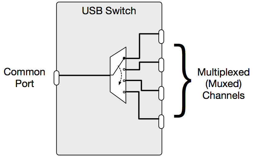
Figure 2: Simplified USB-C-Switch Data path
In order to provide more granular control and monitoring of each side of the switch, the switch functions have been differentiated between the Common Port and the Muxed channels.
BrainStem APIs differentiate these sides of the USB-C-Switch by accessing the Common Port via the USB entity (USB channel 0) and the four Mux Channels (Mux channels 0-3) via the Mux entity as illustrated in Figure 3.
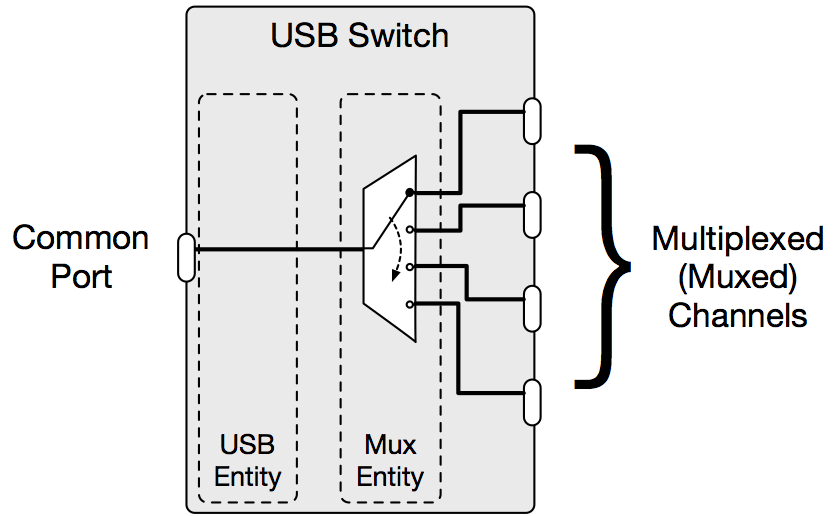
Figure 3: BrainStem view of USB-C-Switch
Common Port/USB Entity
The Common Port is considered a USB entity under BrainStem. Because of this, the USB entity in USB-C-Switch has only one channel USB(0).
Some functions available for the Common Port through the USB entity:
- Enable/Disable
- Entire USB channel
Connect/disconnect the Common/USB side of the switch from the Mux side. All data signal and power lines of the USB port are affected. This simulates and automates a USB unplug/hotplug cycle. - All Data Signals or individually:
- SuperSpeed 1 lane
- SuperSpeed 2 lane
- HiSpeed signals
- All Sideband signals or individually:
- CC1
- CC2
- SBU1
- SBU2
- VBUS/Power
- Entire USB channel
- Monitoring
Measurement functions are not affected by disabling the USB channel- Voltage on VBUS
- Current through VBUS (either direction)
- Voltage on CC1 and CC2
- Current on CC1 and CC2
- USB-C Flip
Conducts a flip of the USB-C connector on USB channel(0). Swaps USB-C connector Side A to Side B and Side B to Side A.
In order to function properly, USB-C Flip functions require use of the Acroname Universal Orientation Cable (UOC), part number C38-USBC-UOC.
Mux Channels/Mux Entity
The multiplexed or channel select side of the switch is considered a Mux entity under BrainStem. Because of this, the Mux entity in USB-C-Switch has three channels Mux(0-3).
Some functions available for the Mux Channels through the Mux entity:
- Enable/Disable
- Entire Mux
Connect/disconnect the Mux side of the switch from the Common/USB side. All data signal and power lines of the Mux are affected. No Mux channel is selected for connection to the Common port. - Channel Select
Selects the Mux channel (0-3) that should be connected to the Common Port/USB entity.
- Entire Mux
- Monitor
Measurement functions are still available even if the Mux (channel connection) has been disabled- Voltage on each Mux channel
VBUS current measurements are not available through the Mux entity. Since current flow will typically only be present on USB-C-Switch when the connection between the Mux and Common/USB is enabled, current monitoring is available only through the USB entity.
Changing Mux Channels
Best practices for changing a Mux channel are to:
- Disable the Common Port/USB
- Change the Mux to the desired channel
- Enable the Common Port/USB
The USB-C-Switch employs a break-before-make strategy to ensure that if different VBUS voltages are present on any channel (due to CC/PD negotiation), that attached devices are not damaged.
Switching the Mux channel by itself can be too fast and cause some USB host drivers to detect an errant condition on the bus. Using the recommended procedure will ensure that the connection between devices emulates a true unplug/channel select/hotplug event.
Example code for changing Mux channels with USB-C-Switch can be found in the BrainStem Development Kit (BDK) under \development\examples.
USB-C Connector Flip
Since standard USB-C cables use internal hardware and strapping to fix connector orientation, the Acroname UOC cable (C38-USBC-UOC) is required to properly conduct a USB-C connector flip (Flip) using USB-C-Switch. Using only standard cables may result in unexpected connectivity errors from your USB host or device.
When configuring an environment for software-based flip of the USB-C connector, the UOC cable should be used. USB-C Connector Flip functions are an advanced feature and will be covered in another blog post. If you do have questions about this, please contact your Acroname sales or techncal representative.
Best practices for conducting a USB-C Flip are to:
- Disable the Common Port/USB
- Common Port/USB Flip
- Enable the Common Port/USB
Issuing the Flip command to the USB channel by itself can be too fast and cause some USB host drivers to detect an errant condition on the bus. Using the recommended procedure will ensure that the connection between devices emulates a true unplug/flip/hotplug event.
Connection Example: Testing Mobile Connectivity
This example illustrates a mobile phone connected to the Common Port. Using USB-C-Switch, we can exercise USB connectivity functions against each one of 4 devices as shown in Figure 4.
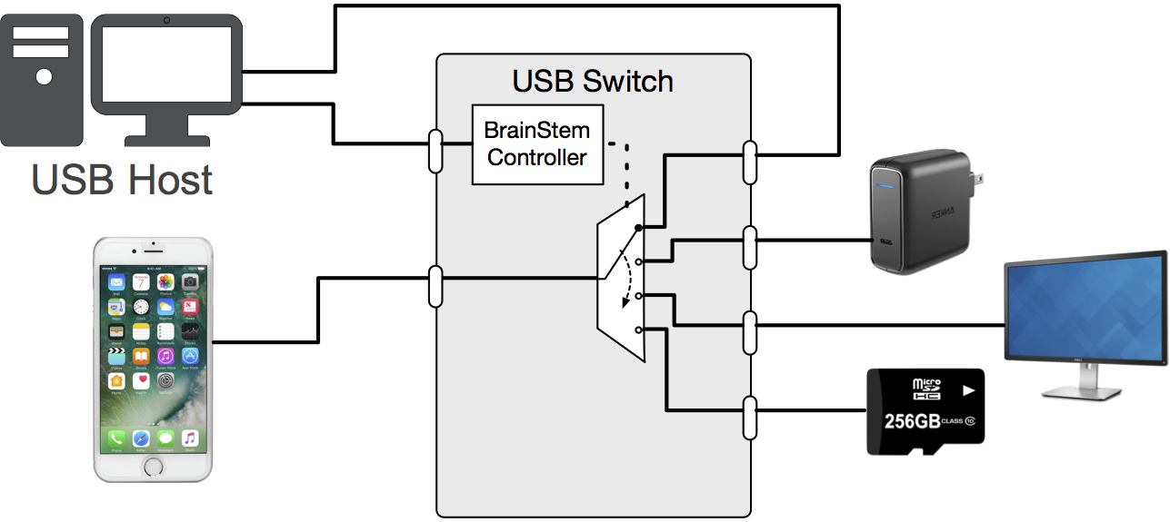
Figure 4: Example of USB-C-Switch automating USB connections to a mobile device
The host executing the tests for the mobile phone is connected to the Control Port in order to control and monitor USB-C-Switch through BrainStem APIs.
The host also connects directly to phone through one the C-Switch mux channels, allowing the host to test the phone’s device-mode behavior and also the host the issue control commands or push firmware updates to the phone.
Here are a few examples of what USB-C-Switch can monitor or automate in each case:
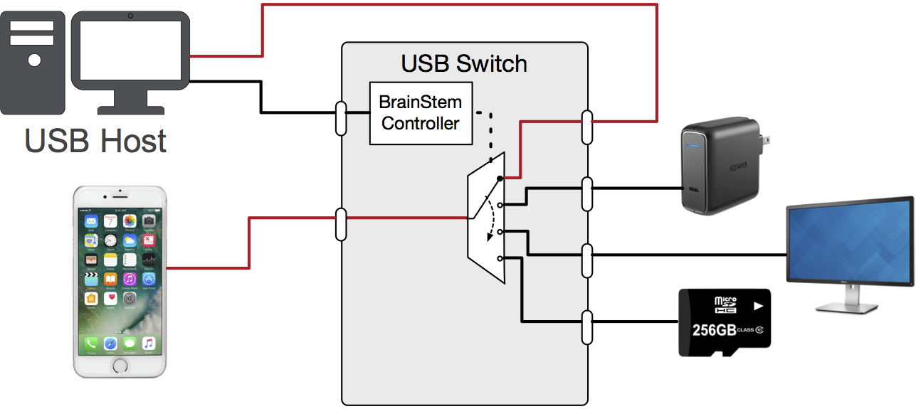
Figure 5: Connecting mobile device to a host
- CH0: Test Control (host)
Phone behaves as a USB device. Host pushes firmware update, issues reboot commands or connects for periodic onboard monitoring- Automate flip of USB-C connector via software (requires UOC cable)
- Verify VBUS voltage and current when charging from host USB
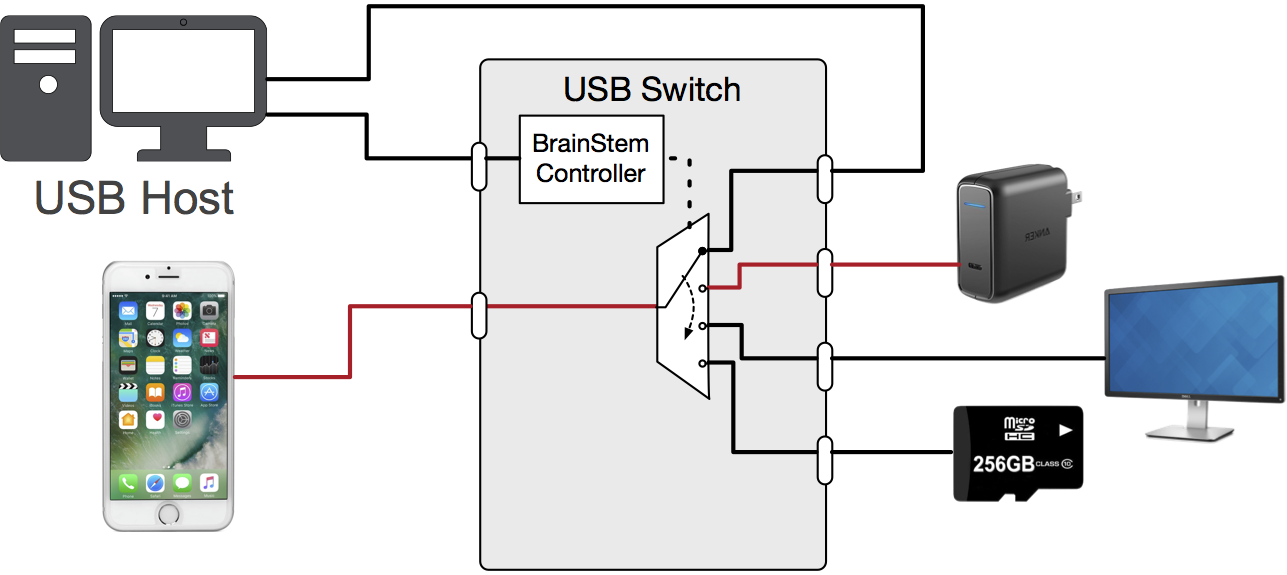
Figure 6 Connecting mobile device to a charger
- Ch1: USB-C/PD Fast charger (charger)
Charger powers the phone- Verify VBUS voltage from the PD charger
- Verify current to the phone from the charger
- Monitor and log power to the phone from the charger vs. on-board fuel gauge
- Test Control Host may switch the phone to this channel periodically to recharge or keep it charged during long test delays
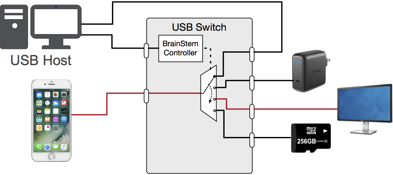
Figure 7 Connecting mobile device to a display
- CH2: USB-C Alt Mode display (display)
Phone drives an Alt Mode display- Enable Alt-Mode connection to the display
- Automate flip of USB-C connector via software (requires UOC cable)

Figure 8 Connecting mobile device to mass storage
- CH3: USB 3.0 mass storage (device)
Phone as a USB host, accesses USB mass storage- Verify VBUS from phone
- Verify current to the USB device
- Automate flip of USB-C connector via software (requires UOC cable)
If you have any other questions or would like to discuss a more advanced application, please contact Acroname’s sales team at sales@acroname.com or our technical team at support@acroname.com .
Add New Comment