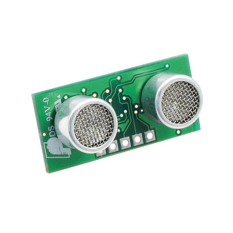
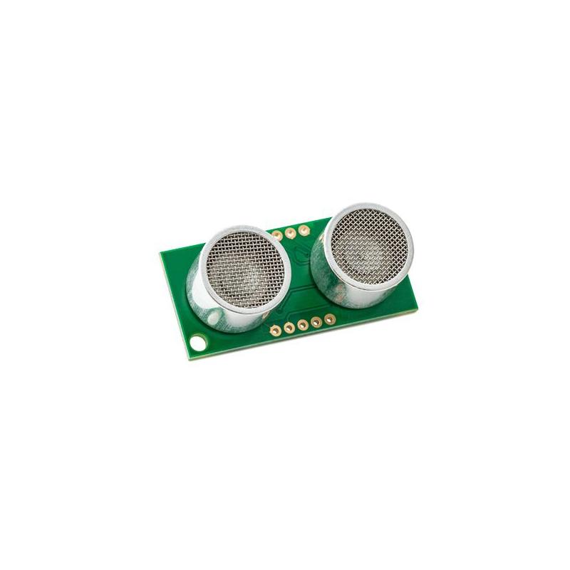
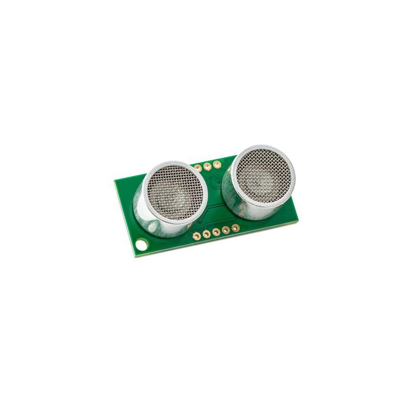
The Devantech SRF10 is an ultrasonic rangefinder with a I2C interface that combines a self-contained design with minimal power draw. Able to measure in both centimeters and inches, the ranging module can measure from 3cm to 600cm (1.2 inches to 19 feet).
Communication with the SRF10 ultrasonic rangefinder is via the I2C bus. This is available on popular controllers such as the OOPic and Stamp BS2p, as well as a wide variety of micro-controllers. To the programmer the SRF10 behaves in the same way as the ubiquitous 24xx series eeprom's, except that the I2C address is different. The default shipped address of the SRF10 is 0xE0. It can be changed by the user to any of 16 addresses E0, E2, E4, E6, E8, EA, EC, EE, F0, F2, F4, F6, F8, FA, FC or FE, therefore up to 16 sonar's can be used. For programming purposes, this module behaves much like the 24xx series eeprom, but with a different I2C address. Connect up to 16 of these sonars together.
Connections
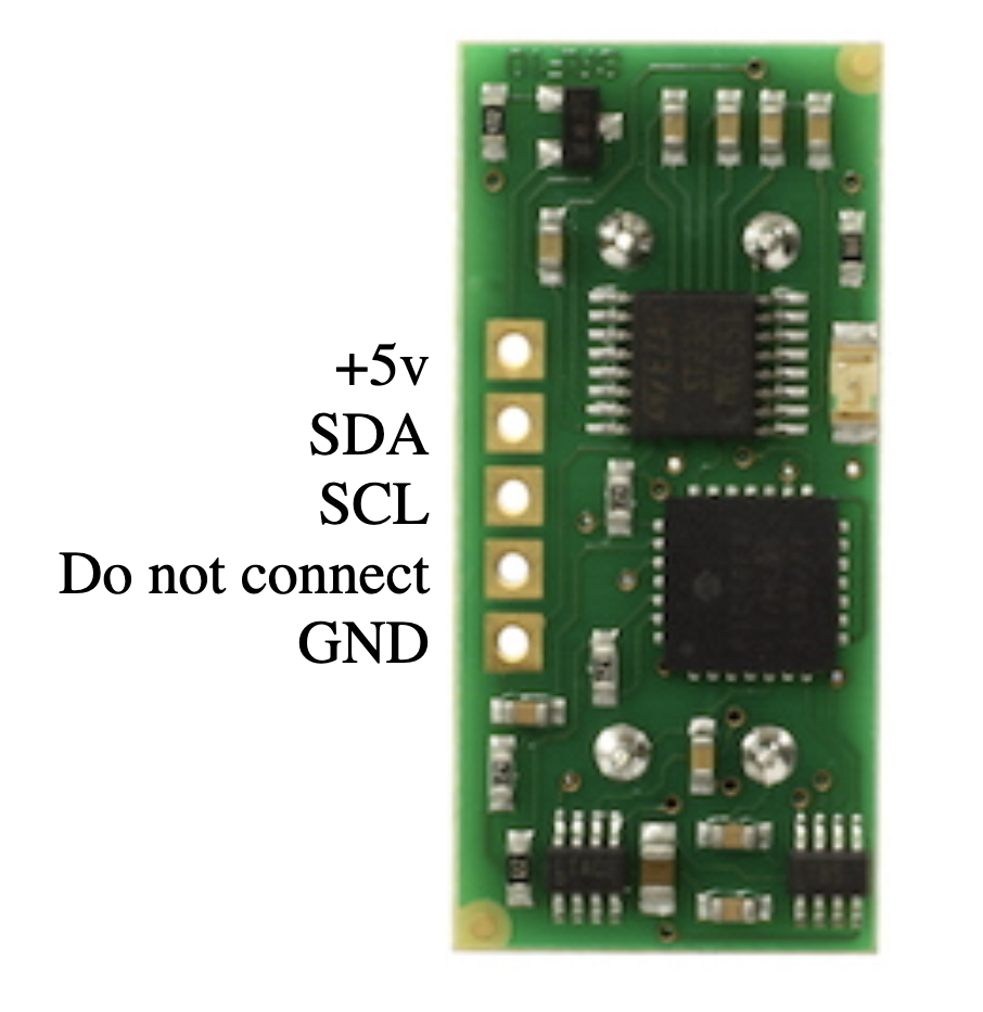
The connections to the SRF10 are identical to the SRF08. The "Do Not Connect" pin should be left unconnected. It is actually the CPU MCLR line and is used once only in our workshop to program the PIC16F87 on-board after assembly, and has an internal pull-up resistor. The SCL and SDA lines should each have a pull-up resistor to +5v somewhere on the I2C bus. You only need one pair of resistors, not a pair for every module. They are normally located with the bus master rather than the slaves. The SRF10 is always a slave - never a bus master. If you need them, I recommend 1.8k resistors. Some modules such as the OOPic already have pull-up resistors and you do not need to add any more.
Ranging Mode
To initiate a ranging, write one of the above commands to the command register and wait the required amount of time for completion and read the result. The echo buffer is cleared at the start of each ranging. The default and recommended time for completion of ranging is 65mS, however you can shorten this by writing to the range register before issuing a ranging command.
Checking for Completion of Ranging
You do not have to use a timer on your own controller to wait for ranging to finish. You can take advantage of the fact that the SRF10 will not respond to any I2C activity whilst ranging. Therefore, if you try to read from the SRF10 (we use the software revision number a location 0) then you will get 255 (0xFF) whilst ranging. This is because the I2C data line (SDA) is pulled high if nothing is driving it. As soon as the ranging is complete the SRF10 will again respond to the I2C bus, so just keep reading the register until its not 255 (0xFF) anymore. You can then read the sonar data. Your controller can take advantage of this to perform other tasks while the SRF10 is ranging.
- Using a 40khz ping the SRF10 measures from 3cm upto 6m. The result can be scaled by the SRF10 to uS, cm or inches.
- No need to worry about timing a response pulse or scaling the result.
- Standard I2C Bus.
Changing beam pattern and beam width
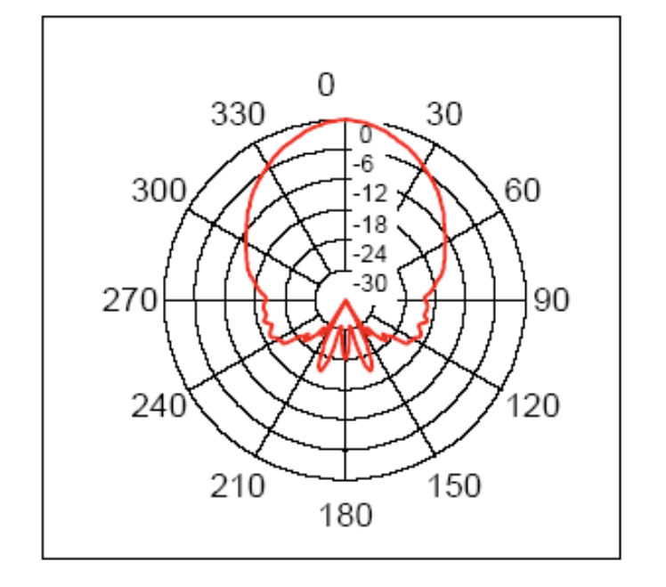
You can't! This is a question which crops up regularly, however there is no easy way to reduce or change the beam width that I'm aware of. The beam pattern of the SRF10 is conical with the width of the beam being a function of the surface area of the transducers and is fixed. It is possible to make the sonar less sensitive to objects off to the side by reducing the maximum gain register from 16 to a lower level. This is a the expense of shorter range, however most small robots don't need 6m of range. A value of 8 (max. gain 140) will reduce the practicable range to about 2m, but it will be much less sensitive to objects off the center line. The beam pattern of the transducers used on the SRF10, taken from the manufacturers data sheet, is shown below.
Mounting the SRF10
You may have notice that there are no mounting holes on the SRF10 module! That was deliberate to keep the module as small as possible. So how do you mount it? Here are three suggestions:
- A straight or right angle 0.1 inch connector soldered to your PCB.
- Using two 9.5mm rubber grommets. Two holes should be drilled into the panel you're mounting the SRF10 to. The hole centers should be 0.7inches (17.78mm) apart and the holes drilled 0.5 inches (12.7mm) in diameter. The two grommets should then be fitted to the panel and the SRF10 gently pushed into them.
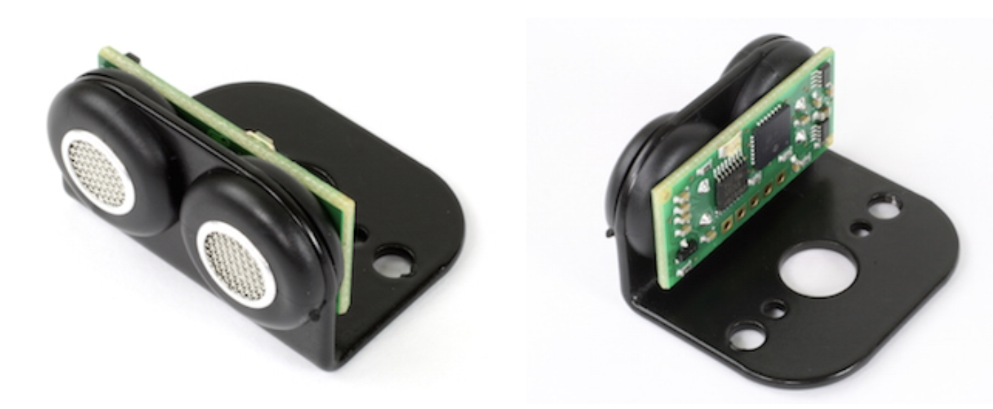
- Using our SRF10 Mounting Kit, shown below.
| Characteristics | ||
| Power | 5V at only 15mA, 3mA in standby mode | |
| Communication | I2C | |
| Distance | 40kHz ping measures from 3cm to 6m | |
| Size | 32mm x 15mm x 10mm |
|
Add New Review