Introduction
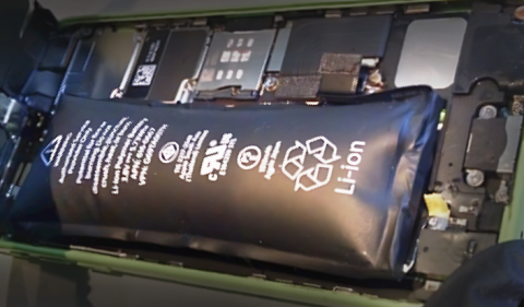
Mobile devices are built to maximize how long they can run between charges by topping off the battery when connected to power. However, in mobile device and Continuous Integration (CI) labs, where hundreds of devices need continuous USB data connections, this presents a challenge. When these devices are USB-tethered for extended periods, the battery is held at a high state of charge (SoC). Long-term high SoC can cause battery swelling and ultimately lead to device failure. In many labs, the mix of devices includes discontinued models that are harder to replace and have already experienced significant battery aging. While there is some disagreement on the exact ideal charge state, around 50% is a reasonable target.
In this post, we show how to maintain a specific state of charge using Acroname’s USBHub3c Industrial USB hub. With control over USB-PD charging and negotiation, the ability to set voltage and current limits, and optional legacy Qualcomm QuickCharge support, USBHub3c lets you keep device batteries in their comfort zone.
Add-on Software Features
To enable control of battery charge, USBHub3c will need these add-on features:
- PD-Builder: Allows customizing local Power Data Objects (PDOs) to emulate various PD source capabilities. Includes Power Rule Editor.
- Vbus Validation Feature: Lets USBHub3c override Vbus voltage set points and current limits. Minimizes data disconnects for non-PD devices.
- PD Logger Feature: Logs PD communications across all USBHub3c ports. Allows reading of Battery SoC for devices that support PD Battery Status.
Optional Add-On:
- Quick Charge: Adds Qualcomm Quick Charge (QC2, QC3) support for legacy devices.
Scalable Test Lab Architecture
Figure 1 shows an example scalable test lab setup. Each test runner unit contains a mini PC (or Mac Mini) as a test runner host, an Acroname USBHub3c Smart USB Hub, and several mobile devices (MD) under test. Testing is managed by a test queue server, with additional runner hosts and racks added as needed to increase capacity. Battery SoC is monitored and controlled by a script on each test runner host.
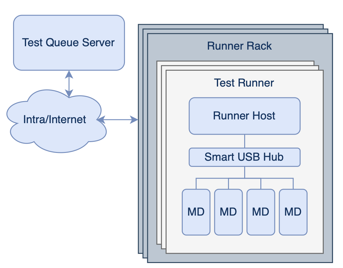
Figure 1: Example scalable test lab architecture
Maintaining a Reasonable State of Charge
When working with heterogenous arrays of devices, multiple charging methods need to be employed, but the basic strategy is the same:
- Read the State of Charge (SoC)
- Control Charging Rate:
- Increase charging if SoC is too low.
- Decrease charging if SoC is too high.
For each device, you will need to determine the lowest power necessary to maintain a data connection. If the lowest connected charge rate is still higher than the average power consumption, the device will need to disconnect periodically to keep the SoC from getting too high.
Reading State Of Charge
To manage battery charging, we need to know the current state of charge. Different devices will require different methods:
- iOS Devices:
- Mac Host: Use Apple’s cfgutil (installs from Apple Configurator)
- Other platforms: Use ideviceinfo from libmobiledevice.
- Android Devices:
- Use Android Debug Bridge (ADB)
- Other devices:
- USB debug modes if available (Note that USBHub3c supports Vendor-Defined Messages)
- OS-level tools via SSH
- Build battery monitoring telemetry into your test application
- USB-PD Battery status:
- Possible using USBHub3c, but not yet widely supported by mobile devices.
In this article, we will focus on iOS and Android devices.
iOS SoC Retrieval:
cfgutil
- Installation: from the Apple Configurator menu, select Install Automation Tools.
- Usage:
list all attached iOS devices to get ECID and UDID for each device:
$ cfgutil list
Type: iPad8,1 ECID: 0x1B69200A96001C UDID: 00007013-001C6A200A65002B Location: 0x1140000 Name: iPad 11
Type: iPhone15,2 ECID: 0x1239D2116B401E UDID: 00008120-001239D2116B401E Location: 0x1130000 Name: iPhone
Request power level for specific ECID, returns SoC (0-100):
$ cfgutil -e 0x1239D2116B401E -f get batteryCurrentCapacity
56
ideviceinfo
Installation (Linux):
sudo apt install libimobiledevice-utils
Usage:
Request power level for specific UDID, returns SoC (0-100):
$ ideviceinfo -q com.apple.mobile.battery -k BatteryCurrentCapacity -u 00008120-001239D2116B401E
56
Android SoC Retrieval
ADB
- Usage:
Request power level for specific UDID, returns SoC (0-100):
$ adb -s D06DA0A03515008J shell dumpsys battery |grep level
level: 55
Controlling the Charge Rate
As a general strategy, we recommend that you confirm that each device performs as expected using the HubTool application to control charge rate. Then add charging features to your control script using the Brainstem API.
How Low Can You Go?
For each device, we need to find the lowest charging current that maintains a data connection and the lowest “high charging rate” that is higher than any expected sustained loads. All devices should stay connected at 500mA.
For PD-Capable Devices
USB-PD device charging can be controlled by setting the Power Data Objects (PDOs) advertised by the USBHub3c. By default, the full range of charging is available, with all PDOs enabled.
- Connect device, observe that device has a USB 2 or USB 3 data connection
- Disable (uncheck) all but PDO # 1 (5 V)
- In the Power Rules Editor, set PDO # 1 current limit to 500 mA. Data should still be connected.
- Lower the PDO #1 current limit to find the lowest setting that allows data connection. This will be the “Low charge current” setting for the device
For Non-PD Devices:
- Use Vbus Current Limiting:
- Set port to CDP mode
- Set VBus current limit to 500mA. Data should still be connected.
- Lower the Vbus current limit to find the lowest setting that allows data connection. This will be the “Low charge current” setting for the device. On many devices, this value is close enough to 500 mA that there is no advantage to going lower.
Pseudocode for Charging Script
Here's what your script should do:
Setup: Device Property Detection:
Retrieve UDIDs and port numbers of all connected devices
- For each USB port:
- Check if a device is connected.
- Check for USB data connection.
- Retrieve the EDID with cfgutil (if iOS device and Mac host).
- Check if the device supports USB Power Delivery (PD).
- If yes, switch port to PD Mode
- If no, switch port to CDP Mode
Low Current Behavior Test:
- For PD Devices:
- Disable PDOs 1-7.
- Set PDO 1's current to 0 mA.
- Check if data connection works with low current.
- For Non-PD Devices:
- Starting at 500 mA, lower the Vbus current limit to 10 mA in 10 mA increments.
- Check if data connection works with low current; store the lowest successful value
Cycle the port if data connection is lost.
Charging Loop:
These are some simple 3-level bang-bang control loops to get you started.
For PD Devices:
- Check if USB data connection is active:
- If not, set PDO 1's maximum current to 500 mA and wait 500 ms.
- Read the SoC:
- If SoC is below 50%: Fast Charge
- Set PDO 1 to 3A and enable all PDOs.
- If SoC is above 55% and it is OK to drop the connection or data works below 500 mA: No Charge
- Disable PDOs 2-7 and set PDO 1's maximum current to 0 mA.
- Otherwise: Medium Charge
- Disable PDOs 2-7 and set PDO 1's maximum current to 500 mA.
- If SoC is below 50%: Fast Charge
- Wait 10 seconds.
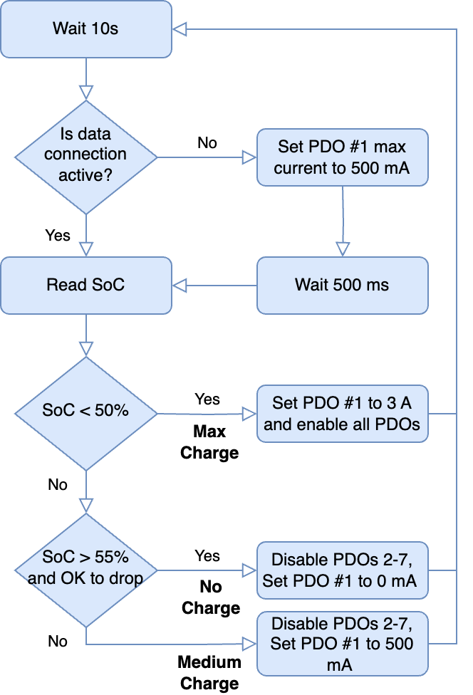
Figure 2: PD device charging flowchart
For Non-PD Devices:
- Check if USB data connection is active:
- If not, set Vbus maximum current to 500 mA and wait 500 ms.
- Read the SoC:
- If SoC is below 50%: Fast charge
- Set the Vbus current to 3 A.
- If SoC is above 55% and it is OK to drop the connection or data works at 10 mA: No Charge
- Set Vbus maximum current to 10 mA.
- Otherwise: Medium Charge
- Set Vbus max to 500 mA.
- If SoC is below 50%: Fast charge
- Wait 10 seconds.
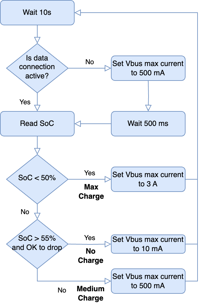
Figure 3: Vbus current limiting for non-PD devices
Useful APIs
Is a Device Connected to the Port?
stem.pd[x].getCableOrientation
- Returns 0 if nothing attached
Is there a Data Connection?
stem.hub.port[port index].getDataSpeed()
- Returns 0 if no data connection
What are the Serial Numbers (UDID) for Devices on each Port?
brainstem.discover.getDownstreamDevices()
- Returns list of connected device information including hub port index and device serial numbers (From USB descriptors)
Is the Device PD-Capable?
stem.pd[port index].getRequestDataObject()
- RDO parameter = 0 for non-PD device
Set Vbus maximum current:
stem.hub.port[port index].setCurrentLimit()
- Set current limit in microamps (µA)
Enable / Disable PDOs:
stem.pd[port index].setPowerDataObjectEnabled()
Set the PDO rule current: (does not enable or disable it)
stem.pd[port index].setPowerDataObject(powerRole, ruleIndex, pdo)
- To find the correct PDO to send, set the desired current for PDO 1 in HubTool and view the “raw” column. The last 3 digits are the maximum current in hundredths of an amp (in hexadecimal).
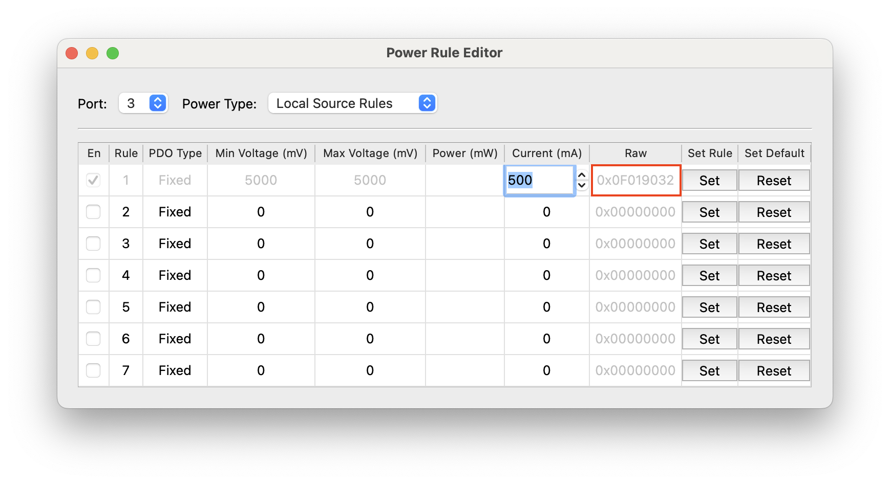
Example raw PDOs for Rule 1:
- 0x0F019000 = set to source to 0 mA,
- 0x0F019032 = set to source to 500 mA
- 0x0F019064 = set to source to 1000 mA
Conclusion
Maintaining a moderate state of charge for mobile devices in test labs helps extend battery life, preventing swelling, and reducing device failure. The USBHub3c, with its power control features, helps manage charging across a variety of new and legacy devices. By using the HubTool app for interactive testing and the BrainStem API for automation, you can implement charging strategies that keep your lab running smoothly.
Add New Comment