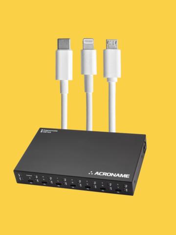
USBHub3c, combined with the External Load Feature, allows easy load testing and battery discharge of a variety of USB devices, including legacy Lightning, USB-OTG and USB-C ports, with and without USB Power Delivery (PD).
Who is this Application Note for?
This guide is intended for users who need to:
- Test, charge, or discharge:
- Legacy Micro USB-OTG devices
- Apple Lightning devices
- USB-C devices with and without USB Power Delivery (PD)
- Maintain battery state of charge in a mixed fleet of USB devices
Specific applications include:
- Device Labs and Continuous Integration systems
- Device testing labs: battery and charge system stress testing, design and feature validation
- End-of-Line battery charging and provisioning
In this note, examples will be use the HubTool application, but all functions can be automated through the BrainStem API.
USB-OTG and Lightning Host Mode Selection
What is USB-OTG?
The USB On-The-Go (USB-OTG) standard allows mobile devices like smartphones and tablets to act as USB hosts - providing power and data connection to peripherals like flash drives, keyboards, and other audio devices.
The OTG specification required the host device to have a USB Micro-AB port capable of connecting to both Micro-B and Micro-A connectors, with Micro-A intended for OTG Host Mode.
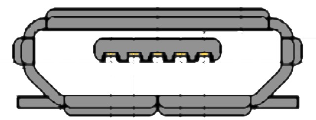
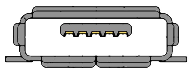
In practice, however, many USB-OTG phones and tablets were built with Micro-B receptacles and nearly all USB-OTG cables included Micro-B connectors on the host side and USB A on the device side. As devices have transitioned to the USB-C standard, USB-OTG has been effectively replaced by USB-C's Dual Role Power (DRP) and Dual Role Data (DRD) functions.
But what about USB-C "OTG" adapters?
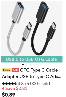
While USB-OTG originally referred to the specific dual-role port feature of the USB 2.0 standard, the term now often describes any USB connection that allows a phone or tablet to act as a host. Usually, these are USB-C to A (f) cables (e.g. Acroname’s C41 adapter), sometimes with additional functions like a headphone jack.
How does a USB-OTG device know to enter OTG host mode?
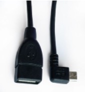
USB-OTG adapter cables (usually Micro-B to USB-A female) include a 5.1 kΩ pull-down resistor on the ID pin. This signals the OTG-capable device to enter host mode and supply 5 V at 500 mA. Power always flows from host to connected peripheral.
Host mode for Apple devices with Lightning ports
Apple devices with Lightning ports use a system for host mode that is like USB-OTG, but with a few key differences:
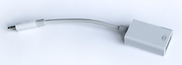
- Requires an Apple Lightning to USB Camera Adapter (or equivalent). This Lightning to USB-A (Female) adapter contains an MFI (made for iPhone/iPad) authentication chip that communicates with the iOS device to enable host mode.
- Provides 5 V, 100 mA
- More limited peripheral support
Host Mode Selection for USB-C Dual-Role Data Ports
How does a USB-C DRP know if it should be a host?
A Dual Role Data USB-C port can function as:
- DFP - Downstream-Facing Port (Host)
- UFP - Upstream-Facing Port (Device)
Since hosts must provide power, all DRD ports are necessarily capable of DRP.
Role determination is done via CC pin negotiation:
- A host-capable device signals its capability by applying pull-up resistors to the CC pins.
- A device-only port signals its capability by connecting pull-down resistors to the CC pins.
- • Dual role data devices alternate between pull-up and-pull down resistors. If two DRD devices are connected, they alternate until one settles as the host and the other as the device.
Once roles are established, the host will provide 500 mA at 5 V for USB 2 connections, and 900 mA for USB 3 connections.
Further negotiation can occur over USB-PD if supported by both devices. USB-PD enables:
- Higher voltages and currents
- Dynamic role swapping
- Independent data and power directions: a host can source or sink power
| Feature | USB OTG (Micro USB port on Host) | USB-C Dual-Role Data Port |
| Power Activation | 5.1 kΩ pull-down resistor on ID pin | CC pin resistor negotiation establishes host/device roles and indicates device present. |
| Host Power Limits | 5 V, 500 mA (2.5 W) |
|
| Cable Type | Micro USB OTG adapter, usually to USB-A (female) | USB-C to USB-C cable |
| Role Switching | OTG Adapter determines host role | Uses CC pin negotiation for initial connection and role. USB-PD adds dynamic role switching with independent data and power directions |
Forcing USB-C DRP devices into legacy USB host mode
While USB-PD offers the most power flexibility, there are several reasons to put dual-role USB-C devices into legacy host mode:
- Test legacy USB host mode support
- Ensure power is available independent of peripheral status
- Simplify discharge testing without USB-PD
- Standardize power control across a mixed fleet of tethered PD and non-PD devices.
Host mode can be forced either by using an adapter cable, or by connecting a peripheral with the correct resistor strapping.
USB-C host selection by cable:
- Connect a USB-C-to-A (female) adapter to the DRD DUT.
- Use a USB-A (male)-to-X cable to connect the peripheral.
How This Works:
The USB-C to USB-A adapter contains 5.1 kΩ pull-down resistors on the CC pins, signaling to the DUT that a UFP sink is attached, even when no device is connected.
- This tells the DUT to enter host mode and provide 5 V on Vbus.
No PD negotiation can occur because the CC lines are not connected end-to-end.
If the peripheral is also USB-C:
Connect a USB-C-to-A (female) adapter to the USB-C port on the DUT as above.
- Connect a USB-A (male)-to-C cable from the C-to-A adapter to the peripheral. A 56 KΩ pull-up resistor on the CC pin tells the peripheral that the source does not support USB-PD and to expect 5 V at 500 mA if USB 2 or 900 mA if USB3.
Alternatively, connect a USB-C to USB-C cable to a peripheral that presents the appropriate CC pin signaling. USBHub3c can be configured to emulate this behavior.
Using USBHub3c to charge or discharge USB-OTG, lightning, and USB-C hosts
USBHub3c can simultaneously charge and discharge up to six devices. Each DUT needs to be connected to its own dedicated load (DUTs can share a load if only one DUT is connected to a power-enabled port at a time). The HubTool application is used to configure and control USBHub3c.
Connections:
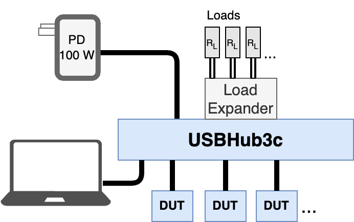
- Connect a USB-C-to-C cable from the test PC to the USBHub3c’s control port.
- Connect a 100W power supply to USBHub3c’s Power C port.
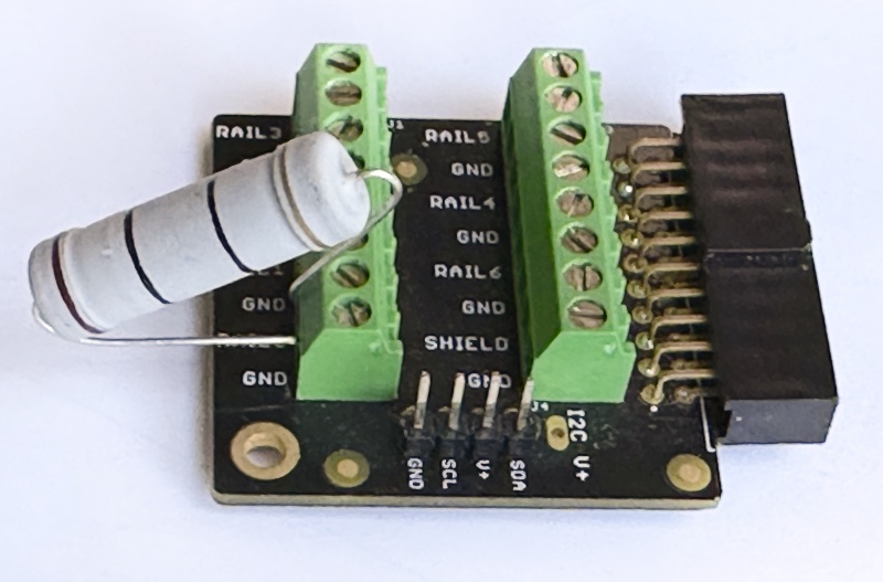
- Attach the External Load Expansion Connector.
- Attach a load (power resistor or programmable load) to the appropriate rail:
- Power resistor: for 5 V at 500 mA, use 10Ω, 5 W or greater
- Programmable load: e.g., MTM-Load-1 with S100-MTM-DEV-3
Connect each DUT (Device Under Test) to a USBHub3c numbered port using the appropriate cable:
USB OTG (Micro USB):
DUT → Micro USB OTG adapter → USB-A to USB-C cable → USBHub3c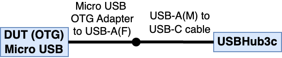
Lightning Camera Connection:
DUT → Lightning to USB camera adapter → USB-A to USB-C cable → USBHub3c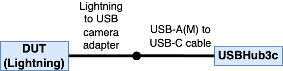
USB-C (Host Mode Test selected by cable):
DUT → USB-C to USB-A (F) cable → USB-A (M) to USB-C cable → USBHub3c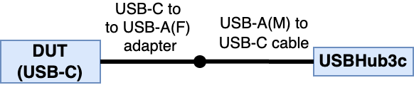
USB-C (Host Mode Test selected by device with or without USB-PD ):
USB-C to USB-C
Discharging without USB-PD
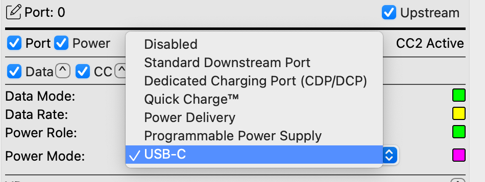
Set Power mode to USB-C (disable the port before changing power mode, then re-enable).
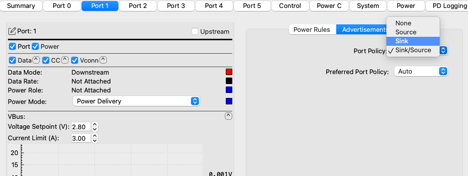
Under Advertisements, set the Port Policy to Sink Mode to accept power from the DUT:
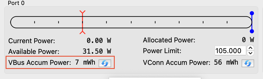
Reset accumulated energy in the Power tab (if monitoring energy).
Under the System Tab, enable the rail.

- If using a programmable load, set to 500 mA and enable.
(enabling rails after the load is enabled can cause voltage spikes) - Observe the port current.
Monitor VBus Accumulated Power.

To stop discharging:
- If using a programmable load, disable it.
- Disable the rail under the System tab.
Charging Devices (non-PD)
For USB-OTG: use a standard Micro USB cable instead of OTG
For Lightning: use a standard lightning cable instead of the Camera Adapter.
For USB-C to A to C: reverse the direction of the cables.
For USB-C: no cable change is needed.
Set Power mode to USB-C (disable the port before changing power mode, then re-enable).
Under Advertisements, set the Port Policy to Source Mode to provide power to the DUT.
USB-PD device discharge and charge
Use the same steps as above but set power mode to USB-PD, and under Power Roles:
If hub is sinking: select desired remote PDOs from the list of available PDOs by Object Position (index)
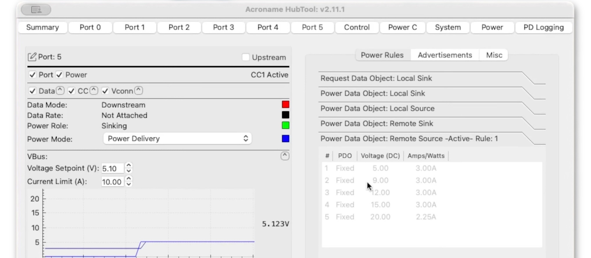
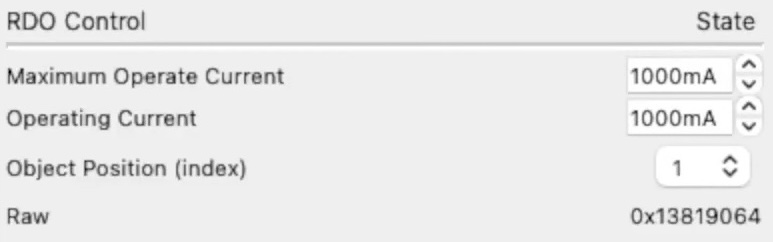
- If testing multiple PD modes, select additional Object Position Indices.
- If hub is sourcing: enable desired local source PDOs
CONCLUSION
USBHub3c simplifies charging, discharging, and load testing of USB-OTG, Lightning, and Dual Role Data USB-C ports - with and without USB-PD. With USB-C negotiation and full USB-PD control, mobile devices can switch between source and sink roles, allowing for battery cycling or state-of-charge control. All hub functions can be controlled interactively through the HubTool application or automated with the HubTool API, allowing simple integration into CI device labs, testing labs, and end-of-line manufacturing test systems.
RESOURCES
Video Example of PD load testing with USBHub3c
HubTool USBHub3c reference
https://acroname.com/reference/software/hubtool/usbhub3c/index.html
External Load Testing with BrainStem API
https://acroname.com/reference/devices/usbhub3c/software_features/external_load.html
Add New Comment