Flexibly Control USB-C Connections
USB-C makes life easy for average consumers and users through two mechanisms: orientation agnostic connectors and automatic configuration. While these features are great for average users, they can make testing and validating USB systems complicated. Acroname's USB-C-Switch exposes much of this complexity to allow engineers to flexibly control USB-C connections including the ability to add cable flips and toggling individual features of the USB-C cabling.
Cable Orientation
First, the concept of cable orientation needs to be defined. For USB-C, the orientation of a connection between a male plug and female receptacle is defined by the male plug. For USB-C, there are two possible orientation of the male plug, which the USB-IF defines as orientation 1 and 2. It is the responsibility of the female receptacle to detect the orientation of the male plug and reconfigure pins on the receptacle to match the plug's orientation.
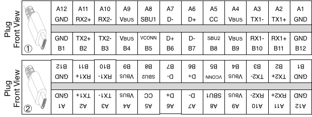
Figure 1: USB-C plug and receptacle pin-out definition and orientations.
When a male plug in orientation 1 connects with a female receptacle in orientation 1, the plug’s A1 is connected to the receptacle’s A1 and similarly for all 24 pins. In this configuration, the plug’s CC pin (A5) is connected to the receptacle’s CC1 pin (A5).
Flipping either connector will a “flip”. That is, A1 will now be connected to B1 and similarly for all 24 pins. In this configuration, the plug’s CC pin (A5) is connected to the receptacle’s CC2 pin (B5). The system needs a way to detect such orientation flips so as to correctly assign relevant pins in the system.
The indication of orientation of for a standard USB-C cable is done with a pull-down resistor (Ra) on the Vconn pin. With this pull-down, the cable is signaling this pin should be used as “Vconn” and the other pin should be used as “CC". Active cables behave similarly, and can actual draw some current from Vconn to power “e-marker” authentication circuits in the cable.
It is clear that flipping the orientation of one end of a standard cable does not affect the other end. That is, the CC and Vconn wires go straight through the cable. As such, each USB-C male connector must define its orientation so that pin defined as CC on one end of the cable is connected to the pin defined as CC on the other end.
Beyond the cable, the female receptacle has two roles in interacting with the USB-C male plug: providing a pull-up resistor (Rp) to both pins labeled CC on the connectors and sensing voltages on these pins to determine the presence and orientation of a connected male plug. These pull-up resistors are the start of the USB Power Delivery (USB-PD) specification, of which this article will only scratch the surface. Suffice to say that if the USB-C receptacle supports sourcing power, it will provide a Rp on both CC pins.
Alternatively, if the female receptacle supports sinking power, it will provide an pull-down resistor (Rd) on both CC pins. Devices with captive cables or built-in USB-C male plugs (e.g. flash drives), should also present Rd on both CC pins. For devices which support sourcing and sinking power, the female receptacle will toggle between a Rp and Rd on both CC lines.
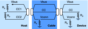
Figure 2: USB-C simplified Rp, Ra and Rd locations.
USB-C-Switch Illustrates This Behavior
The following images, captured from StemTool, show the USB-C-Switch’s measurement of CC pin voltages when there is nothing connected on any of the USB-C-Switch mux ports and the common-port is connected to a host-PC’s USB-C female receptacle using an Acroname’s Universal Orientation Cable (UOC) as well as a standard USB-C cable. One of the features of the UOC cable is that it does not provide the standard Ra.
By doing so, it appears as a transparent “port extension” from the connected host-PC to the USB-C-Switch common-port. In this configuration, figure 3 shows that both CC lines are toggling between 0V and 3.3V. This is behavior shows that the host-PC supports sourcing and sinking power from this port. After replacing the UOC with a standard USB-C cable, figure 3 shows that CC1 continuous to toggle between 0V and 3.3V while CC2 stays near 0V.
The 0V on CC2 is caused by the presence of Ra in the standard USB-C cable, and indicates that the connected cable is in orientation 1 on the end connected to the USB-C-Switch common port. Note that in both cases Vbus stays near 0V.
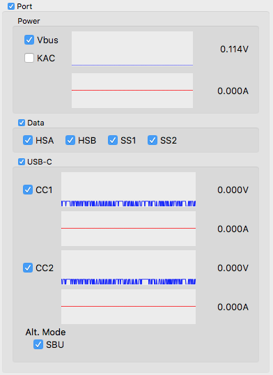
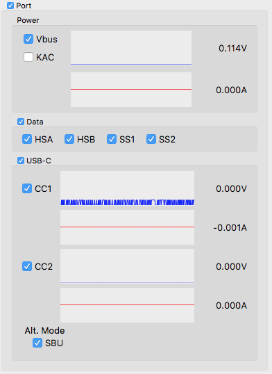

Figure 3: USB-C-Switch measurements in StemTool when connecting a host-PC through (a) an Acroname UOC and (b) a standard USB-C cable.
USB-C-Switch and You!
In a system without the USB-C-Switch, there would be only one cable connecting two devices (e.g. host-PC -> USB-C cable -> mobile device). The USB-C-Switch effectively splits this one cable into two, making the system have two USB-C cables (e.g. host-PC -> USB-C cable -> USB-C-Switch -> USB-C cable -> mobile device). Note that in a system without the USB-C-Switch, it would be impossible to have two USB-C cables since USB-C cables are defined to always be male-to-male. Since the USB-C male connector defines the orientation of the system, a system with two standard USB-C cables (or any combination of USB-C to type-A or type-B) breaks the “magic” of orientation agnostic connections.
Signaling Chain Issues
That is, the orientations of the multiple USB-C male connector may not agree through the whole signaling chain. If this happens, there would be two pins which are indicated to be Vconn and no pin indicated as CC. When this happens, it can be impossible to get USB devices to communicate or power up on the USB bus.
Device Charging Issues
If devices will charge but cannot connect USB data through the USB-C-Switch, or if device cannot charge nor enumerate on USB, there might be a conflict in the the orientations of the cables in the system. The USB-C-Switch firmware attempts to detect cable orientation when the USB entity's port mode is set to "usbPortMode_AutoConnectEnable".
However, there are times where this feature may be problematic for a particular test condition or fails to detect particular cable configurations. The StemTool GUI can be useful to help debug these issues and determine the proper cable orientation for the system.
Starting with the previous system and adding a downstream device to the system, the USB-C-Switch can help to illustrate when cables are properly orientated. For these tests, a downstream device which has a USB-C female receptacle is connected to the mux port 0 of the USB-C-Switch with a standard USB-C cable.
When a UOC is used between the host-PC and the common-port and then downstream device is connected, several things happen. Since the standard USB-C cable has Ra, the voltage on CC1 stops toggling and becomes a constant 1.6V. The CC2 pin also stops toggling and goes to a constant 5.0V. Further, the VBus goes from 0V to 5.0V and the downstream devices start to sink current.
All of these behaviors indicate a properly connected system between there host-PC and the downstream device where the USB-C switch is acting as a transparent mux.
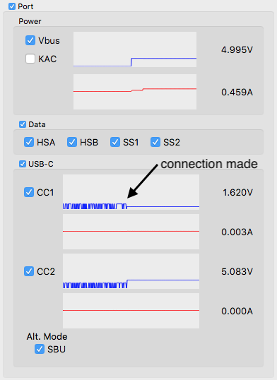

Figure 4: USB-C-Switch measurements in StemTool when connecting a host-PC through an Acroname UOC to a USB-C-Switch and then through a standard USB-C cable to a downstrem device.
Replacing the UOC cable
Using a standard USB-C cable between the host-PC and common-port can lead to an issue. There are two possible orientations for the USB-C male plug on the mux port, and it is impossible to know a-priori which orientation will get connected. Again, StemTool’s measurements can help.
In figure 5, after the downstream device gets connected to the mux port, CC2 stays at 0V and CC1 stops toggling and drops to near 0V. CC1 has stopped toggling because the USB-C cable between the mux port and the downstream device has an Ra on CC1. This happens because the system has and Ra on both CC pins. In a normal USB-C system with only one cable, this could never happen. In this configuration, Vbus stays near 0V and the downstream device does not enumerate on the host-PC.
Now, simply flipping the orientation of the USB-C cable between the mux port and the downstream device causes the CC1 voltage to go to 1.6V, CC2 stays near 0V, Vbus goes to 5.0V and the downstream device starts sinking current. Measurements during this manual cable flip are shown in figure 6.
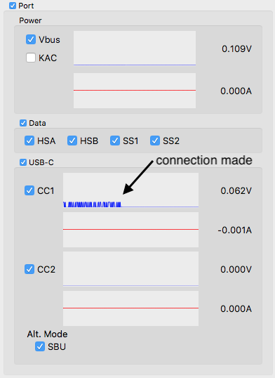

Figure 5: USB-C-Switch measurements in StemTool when connecting a host-PC through a standard USB-C cable to a USB-C-Switch and then through a standard USB-C cable to a downstrem device with improper cable orientation alignments.
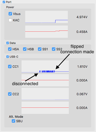
Figure 6: USB-C-Switch measurements in StemTool when connecting a host-PC through a standard USB-C cable to a USB-C-Switch and then through a standard USB-C cable to a downstrem device showing a manual cable flip going from improper cable orientation alignments to proper orientation alignments.
Cable Flip Without Touching Cables
Through the above process, StemTool has enable the determination of a proper cabling orientation for a particular setup using two standard USB-C cables. And it gets better! With the USB-C-Switch the flipping of the cable can be done without having to touch the cables. Figure 7 shows the effect of using the “cable flip” feature when starting with the non-functional configuration above where there were Ra’s on both CC pins.
Simply enabling the cable flip feature effectively moves the Ra on the from CC2 pin to the CC1 so there is no conflict. This allows the CC1 voltage to stay near 0V, while the CC2 voltage to go to 1.6V, Vbus to goes to 5.0V and the devices starts sinking current. The downstream devices also enumerates on the USB bus.

Figure 7: Using the USB-C-Switch to apply a cable flip to in a system with a improper cable orientation alignment.
Legacy Cables
USB-C cables which convert from the old USB type-A, type-B (or mini-B or micro-B) standards need to perform similar roles in indicating the male USB-C plug orientation, and also need to define other USB roles. For example, a USB type-A male to type-C (A-to-C) cable needs to define that the type-A male side of the cable is a power provider (source), since the legacy USB specification defined that type-A socket connectors could only be a source of power and not a sink. Also, the cable needs to define that it is a legacy cable that does not support USB-PD so connected devices can fall back to the USB Battery Charge (USB-BC) specification.
Male-A-to-C cable
To accomplish this, a male-A-to-C cable includes a pull-up from Vbus on the type-A end to CC on the USB-C male plug. The Vconn pin on the USB-C male plug is left unconnected. With a female-A-to-C socket adapter, the USB-C CC pin will be pulled low with an Rd to indicate to the USB-C device that the connected cable is non-PD sink and it needs to enable BC1.2 compliant Vbus of 5V. That is, a female-A-to-C adapter will appear to a USB-C system as if a non-PD device is attached.
USB micro-B to USB-C
Another useful legacy cable example is a going from USB micro-B to USB-C (µB-to-C). In this case, the cable needs to define the orientation of the USB-C male plug and also define that the micro-B side of the cable is a power sink. Similar to the female-A-to-C cable, devices in the system need to fallback to the USB-BC standards and disable special USB-PD features. To accomplish this, the cable connects an Rd on on the CC pin of the USB-C male plug and leaves Vconn unconnected.
As with systems using more than one standard USB-C cable, using legacy cables with the USB-C-Switch can lead to connections with improper orientation alignments. In many cases when using legacy cables, devices may charge but not enumerate on the USB data bus. This can be quite confusing, and again measurements using StemTool can help to debug the cable orientations.
Add New Comment