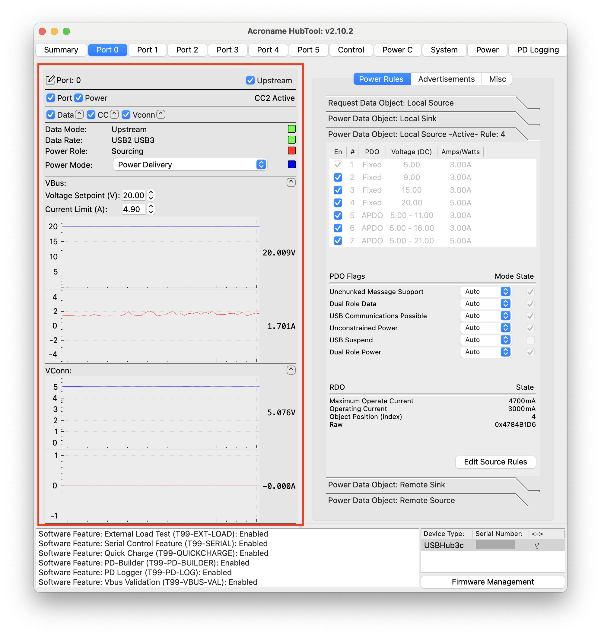
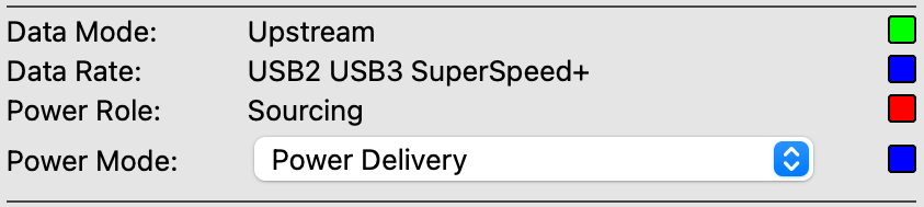
Below the toggles are data mode, data rate, and power role status indicators, followed by the power mode menu. The virtual LED color corresponds to the color of the real LED indicators on the USBHub3c front panel.
Qualcomm® Quick Charge™ 2.0 and 3.0 fast charging, requires Quick Charge feature license
3 A
Green
PD
Power
Delivery
USB-PD revision 2.0 and 3.2 compliant
PD fixed voltage 5 - 20 V up to 5 A,
USB PD-PPS and QC 4+ variable voltage up to 5 - 21 V, 5 A
Blue
PS
Programmable
Power
Supply
Manually set 2.8 V – 21 V and 0 A – 5 A, requires VBus validation feature license
White
USBC
USB-C
5 V, 3 A
Purple
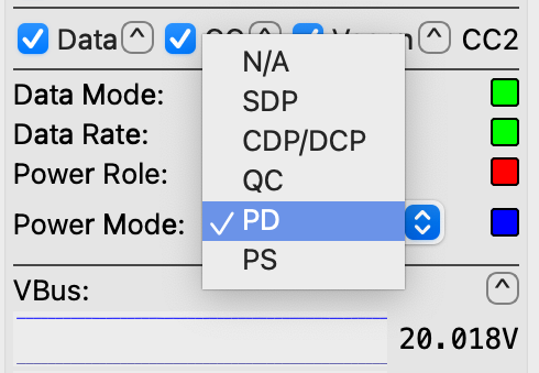
In USB-C and PD modes, the VBus is only enabled after strapping resistors are detected on the CC lines, while SDP, CDP/DCP, PS, and QC modes provide VBus continuously.
In CDP and SDP modes, the port acts as a source if downward facing, and a sink if upward facing.
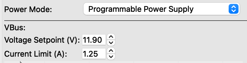
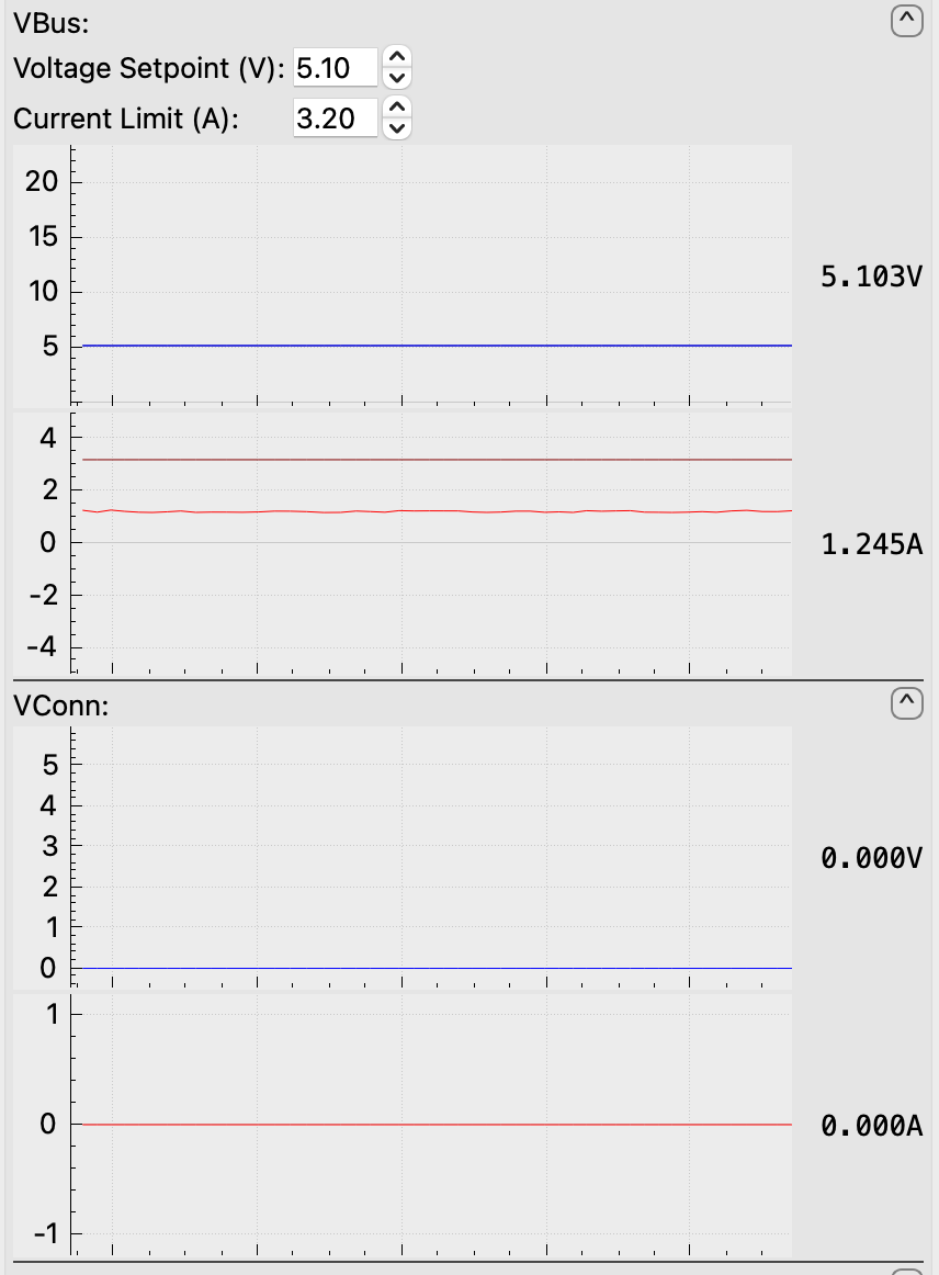
When Programmable Power Supply (PS) mode is enabled, VBus voltage setpoint and current limit can be set directly, transforming the port into a programmable power supply capable of supplying up to 100 Watts. These are saveable settings (System tab / Save) that persist through reset.
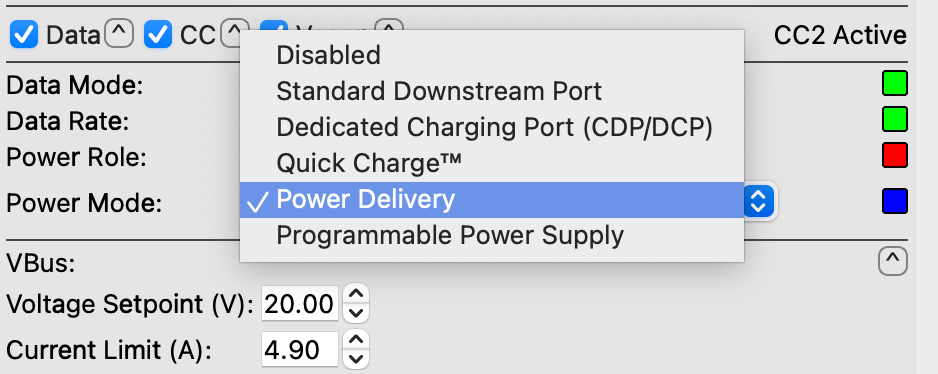
In Power Delivery (PD) mode, the user-set values override the negotiated values. However, PD negotiations are still active and PD events or errors can trigger re-negotiation, which will replace the user-set values. These values should only be changed when the power role is set to sourcing.
In USB-C, SDP, CDP/DCP modes, VBus settings revert to 5 V and default current on port connect or disconnect.
Shows a graph of the VBus and VConn voltage and current of the port.
VBus and VConn panel view
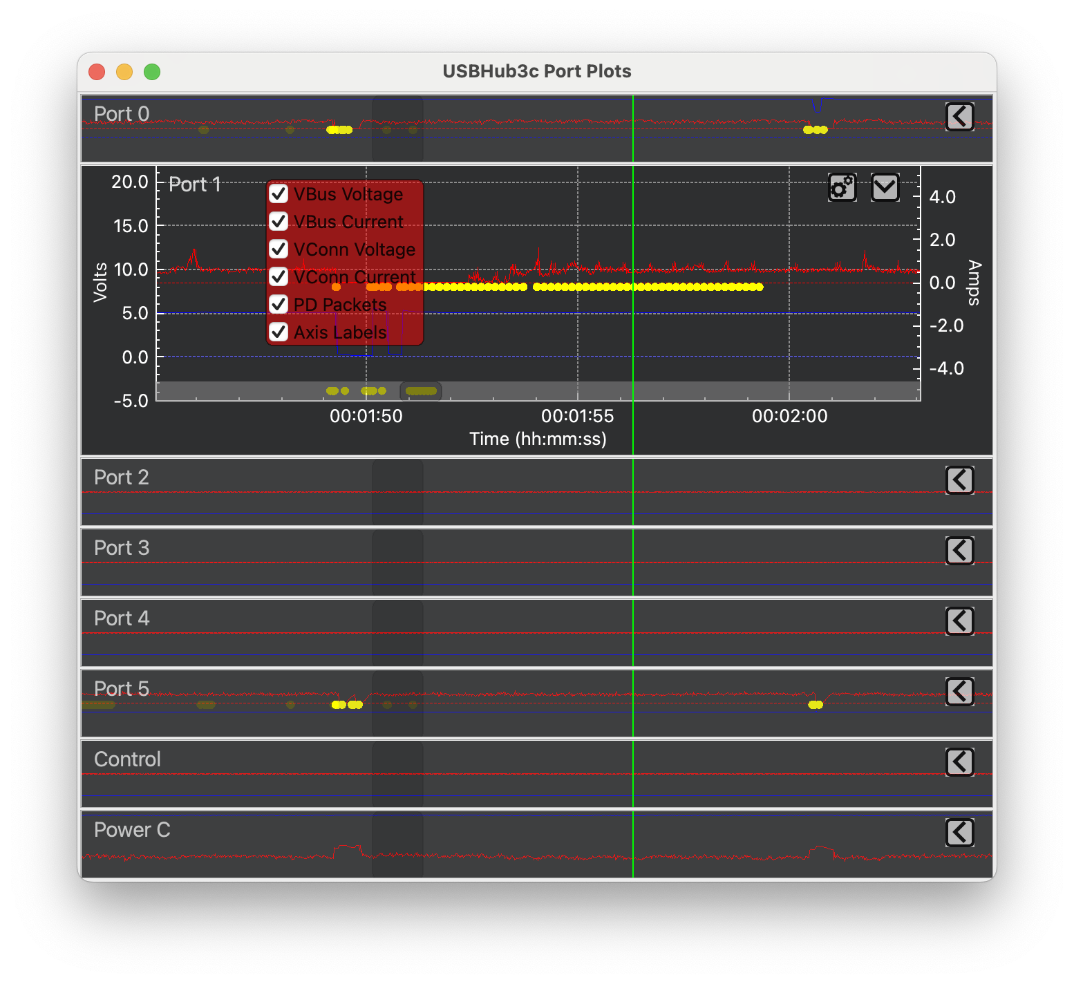
Clicking on the port graph pops up the Port Plots window with a larger rolling strip chart showing all ports. Click the carat ()to expand each port chart. If PD logging is enabled, PD messages will be marked in yellow.
Port Plots window
Left vertical axis – voltage (V)
Right vertical axis – current (A)
Horizontal axis – time (s)
By default, the plot will be scrolling. To stop scrolling, drag the dark gray scroll bar to the left. To enable scroll-to-zoom, click the desired axis.
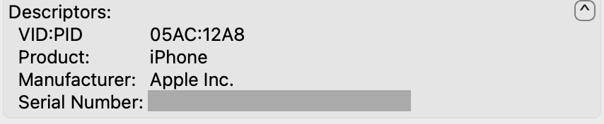
If Options > Port Mapping is selected, when a device is attached to a downstream port, its descriptors will scroll at the bottom of the port panel. Click the carat () to expand:
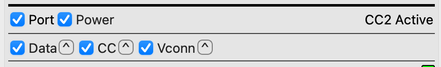
 ) - friendly port name used by HubTool and ControlRoom)
) to expand the view. Clicking the Data carat again cycles through views.
Green
Red
White
Yellow
Blue
Black
Purple
)to expand each port chart. If PD logging is enabled, PD messages will be marked in yellow.