What a USB-C switch is
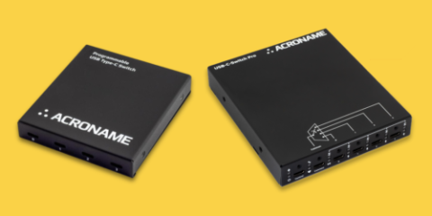
USB-C-Switch (S85) and USB-C-Switch Pro (S110) are managed USB-C switches, not hubs. Each creates a direct, bidirectional 1:1 connection between a common port and one of four mux ports. To connected devices, the active path behaves like a USB-C cable.
There is no hub controller in the data path. USB-C behavior (Power Delivery negotiation, Alternate Modes including DisplayPort, and role swaps) is handled by the connected devices. The switch routes the underlying USB-C signals and can, when needed, independently enable or route signal groups. Unlike a hub, the switch selects which ports are connected.
Common to both
- Managed 1:4 / 4:1 USB-C switch
- Not a hub; no aggregation or fan-out
- Direct, cable-like connection between ports
- Supports USB-C Alternate Modes (e.g., DisplayPort)
- Software-managed via HubTool and BrainStem API
- Test both sides of a port with virtual "cable flip" when using Universal Orientation Cables (UOC)
- Advanced routing features, including split / selective signal routing (use with care)
- Direct connection is ideal for Android Auto and Apple CarPlay development
Key difference
| Category | USB-C-Switch | USB-C-Switch Pro |
|---|---|---|
| Max USB-PD power | Up to 100 W (USB-PD SPR) | Up to 240 W (USB-PD EPR, incl. PPS & AVS) |
| Data rates | USB 3.2 Gen 2 (10 Gbps), USB 2 | USB4 & Thunderbolt 3 (40 Gbps), USB 3.2, USB 2 |
| DisplayPort Alt Mode | DP Alt Mode up to 4K @ 60 Hz | DP 2.1 Alt Mode, up to 2x8K @ 120 Hz |
| Signal handling | Passive or redriver models | Active redrivers on all high-speed paths |
| Measurement & monitoring | VBUS, CC, VCONN voltage and current monitoring | Expanded monitoring: VBUS, CC, VCONN, SBU / AUX; USB-PD message logging, decode, and injection |
| Control interfaces | USB control port | USB, Ethernet, RS-232, I2C, GPIO |
| Automation & integration | BrainStem API, HubTool, AV integrations | BrainStem API, HubTool, web / REST, AV integrations |
| Typical best fit | Lab / manufacturing: USB-C product development, USB 3.x validation, PD testing up to 100 W, signal integrity testing (Passive model). AV: USB 3.2 and 4K DP Alt Mode switching | Lab/ manufacturing:: USB-PD EPR, USB4/TB3 and DP 2.1 validation, manufacturing test at scale, Ethernet-based automation. AV: Ethernet-managed USB and DP 2.1 Alt Mode switching |
The expanding USB-C performance envelope
USB-C has not progressed as a clean sequence of generations. Many products remain 5 V, low current, and USB 2.0.;That class of device is not going away anytime soon.
What has changed is the operating range. The same connector now spans low power and low bandwidth through USB4-class data rates and EPR power. This wider range puts new demands on switching, test, and automation infrastructure.
On the power side, USB Power Delivery has grown from early fixed profiles to 100 W SPR and now 240 W Extended Power Range (EPR). Higher voltages and currents increase sensitivity to connector wear, cable variation, and attach-time transients, especially under repeated plug and unplug cycles.
On the data and video side, USB4/Thunderbolt-class data and to DP 2.1 increases sensitivity to signal integrity for mode entry, re-attach, and cabling.
USB-C-Switch Pro exists to support extended power and data ranges and provides protocol-level visibility, not just pass/fail results.
Why higher power (EPR) is driving many upgrades
In practice, most upgrades we have seen so far are being driven by power, not bandwidth. Validation and compliance labs need to stress-test port EPR support, often involving frequent plugging and unplugging, mixed cable populations, and edge-case negotiation scenarios. Many EPR workflows involve manual cable swapping between DUTs and test instruments or reference devices.
EPR isn't just more Watts. It adds new PD negotiation states, extended messages, and stricter cable and role requirements, increasing the risk of attach and negotiation failures. Debugging benefits from seeing CC activity and PD messages time-aligned with corresponding VBUS voltage and current measurements.
For EPR-capable programs, engineers need to monitor what real devices are actually doing. This shortens triage and can catch marginal cases that eventually succeed after failed negotiations.
When USB-C-Switch is still in scope
It fits when USB-PD requirements are 100 W or below, data paths are up to USB 3.2, and DisplayPort Alt Mode is 4K or below. The passive USB-C-Switch version is used in situations where adding active elements into the channel would be a problem, for example, in signal integrity testing and characterization.
If USB4/TB3 and EPR are out of scope for the program lifecycle, and there is no need for Ethernet management or PD message decoding, the Pro features set is not required.
What USB-C-Switch Pro adds
Primary use cases
In lab and manufacturing environments, USB-C-Switch Pro is used to validate EPR-capable ports, exercise USB4 and DP 2.1 paths, and support automated regression and manufacturing test. Ethernet control means that the control host does not need to be co-located with the switch.
In AV and conference room systems, USB-C-Switch Pro supports switching of higher-resolution DisplayPort Alt Modes and high-bandwidth USB4/TB3 data with centralized Ethernet management and AV platform integrations.
Power headroom
USB-C-Switch Pro supports EPR-class voltage operation. This enables automated attach/detach cycling, power-path selection, and stress testing across multiple ports or devices without manual cable swaps.
Protocol-level visibility
USB-C-Switch Pro adds PD message logging, decode, and injection. It also exposes SBU/AUX activity used by DisplayPort Alt Mode. These signals matter in workflows where failures occur during negotiation, mode entry, or re-attach rather than during steady state.
PD injection supports observation of DUT behavior under invalid or unexpected messages and sequencing, including renegotiation timing errors and reset recovery behavior. Note that this is primarily a triage and characterization capability. It does not replace compliance tooling.
Ethernet, RS-232, I2C, AND GPIO CONTROL
The Ethernet control interfaces allow USB-C-Switch Pro to integrate into automation systems, shared validation labs, and managed AV environments without a locally attached control host, adding flexibility to system layouts.
RS-232, I2C, and GPIO allow the USB-C-Switch Pro to both control or be controlled by external equipment. This allows for a test fixture to manage port switching without a control host, or for a script on the control host to both handle USB switching and drive external equipment.
Decision guide
USB-C-Switch fits when:
- USB-PD requirements are SPR 100 W or below
- USB 3.x and 4K DisplayPort Alt Mode are sufficient
- Signal integrity characterization requires a passive switch
USB-C-Switch Pro fits when:
- USB-PD EPR validation is required
- USB4/TB3 or DP 2.1 is in scope
- Protocol-level PD visibility is required
- Ethernet-managed control is a scaling or placement constraint
Selecting under evolving constraints
USB-C-Switch and USB-C-Switch Pro cover different operating ranges. Selection is driven by present requirements for power, data rate, and visibility, plus whether those requirements are expected to expand within the program lifecycle. It is common to deploy USB-C-Switch for established USB 3.x / SPR programs and reserve USB-C-Switch Pro for EPR, USB4, and DP 2.1 validation and integration work.
Add New Comment